¶ Introduction
Plantwide code is not confined to one process unit (PU) but uses variables from all over the plant model. A template plantwide Excel file for the plantwide code can be opened directly from the GUI (Tools tab) or from the Project directory (View|Directories|Project directory|plantwide.xlsx). In this tutorial the observed sludge yield will be calculated using SumoSlang on the example of Tutorial plant.
¶ IMPORTANT NOTE
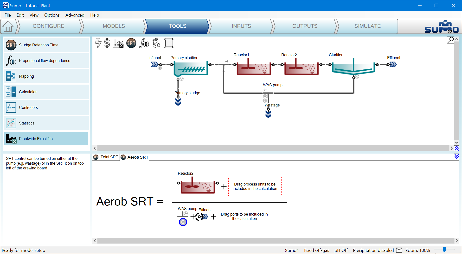
Before proceeding further, remove the control flags from both SRT calculations in the example file using the method from the User manual, Figure 3.13 – Toggling between pump selection for target SRT control.
¶ Goal of calculation
The observed sludge production will depend on the SRT (higher SRT leads to lower sludge production) and the SRT directly depends on wastage flow. Total SRT is already defined in Sumo for Tutorial plant (see the User Manual for how SRT calculation can be added).
The observed yield is defined as solids generated per total COD (or BOD) removed in the plant:

Where:
| Symbol | Unit | Name |
| Yobs | gTSS/gCOD removed | Observed yield of sludge production |
| F.XTSS | gTSS/d | Mass flow of total suspended solids |
| F.TCOD | gCOD/d | Mass flow of total COD |
| F.SCOD | gCOD/d | Mass flow of soluble COD |
In this example we will be both calculating the net yield and also observe the relationship between wastage flow and sludge retention time.
¶ Using a direct algebraic expression for control
PWE Equation 1. can be solved for the required wastage mass flow rate to maintain a certain Yobs,target. Since the model calculates waste solids concentration, the required flow can be expressed.
Definition of the Yobs and wastage control to maintain a desired Yobs,target is carried out by establishing the plantwide code available in Sumo using the necessary variables in the relevant process units.
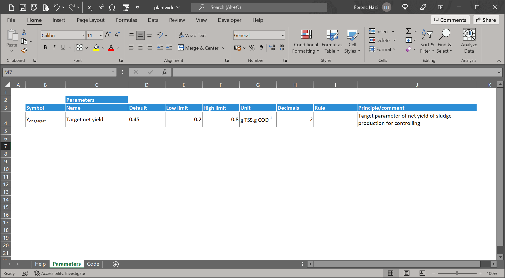
Define the values for any parameters used in the code on Parameter sheet (PWE Figure 3.). These values can be modified on the Input setup tab in the GUI later on.
¶ Variable names used in the code
When writing code, the Incode names of the process units and Symbols of variables have to be used. The general way to write variable names in the plantwide code:
| Variables in process units or pipes | Parameters in process units | ||
|---|---|---|---|
| Process units | Process unit name..variable | In expression | Process unit name..parameter |
| Pipe | Pipename..variable | To Control/Set | |
| Model parameters | |
|---|---|
| Global | Model name..parameter |
| Local | Sumo__Plant__Process unit name__Model name__parameter |
As the engineering names used by the GUI may differ from the names in the code, make sure to use the correct forms, go to:
- View|Advanced|Variable identifier|Switch to Symbol (PWE Figure 4a).
- View|Advanced|Name types|Switch to Incode names (PWE Figure 4b).
The pipe names can be used for calculation therefore pipe names are also need to be shown (View|Show pipenames).

|

|
There are different ways to access/verify these valid forms of names.
¶ Output setup
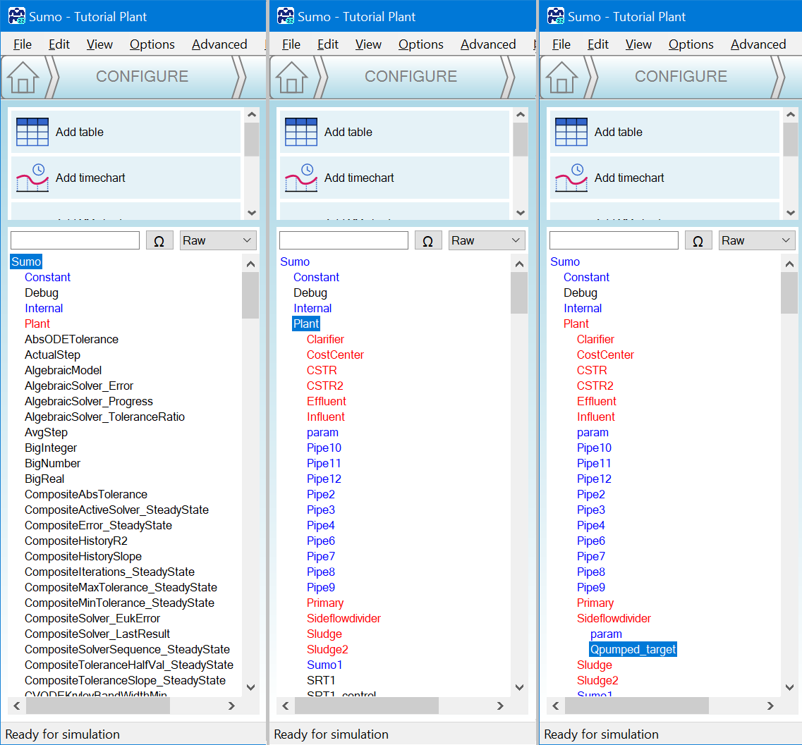
Output Setup tab, left bottom pane, changing the search method to “Raw” and clicking through to the relevant process unit (PWE Figure 5). Here the list shows the Sumo names and proper form of symbols. Concatenate the name with the namespace symbol as shown above:
| Parameters in process units | |
|---|---|
| In expression | Sideflowdivider..Qpumped_target |
| To Control/Set | |
¶ Advanced core window
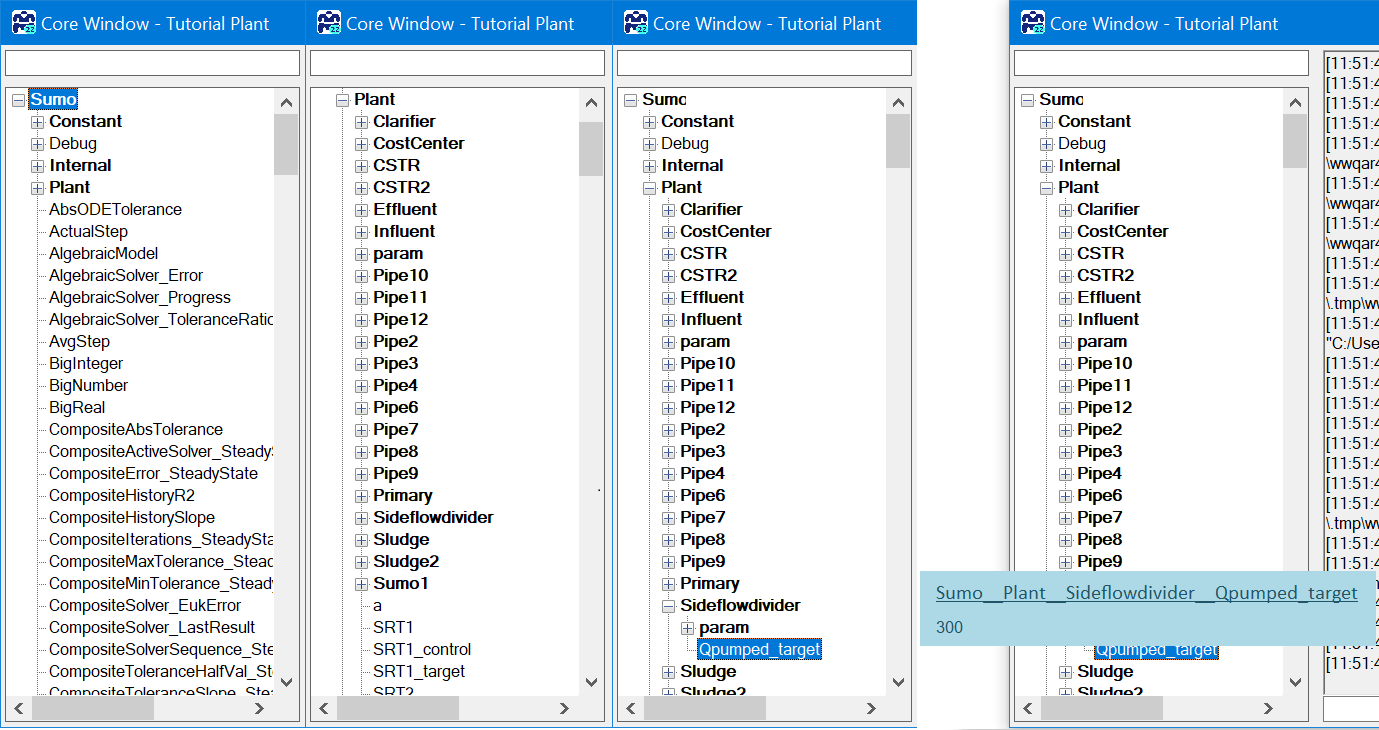
Open the advanced core window: View|Advanced|Core window. On the left panel all the variables and constants are listed (PWE Figure 6). Opening the relevant process unit and hovering over the symbol of the variable, the namespaced symbol appears. Use this form, excluding the Sumo__Plant namespace. Double underscores are namespace separators.
¶ Process Code
Specific variable names can be found also directly in the code View|Directories|Install directory|Process Code|Process Units the process unit parameters and View|Directories|Model directory for the model parameters and variables. This way the MS Excel sheet is opened where you will find not only the symbols but the descriptive names of the variables to avoid confusion.
During the calculations, the port names are not used in this version, so when a variable is needed from a specific input/output port please look for the connected pipe. In case of large configurations to find the connected pipe, a PU search tool can be found on the drawing board (PWE Figure 7).

¶ Project directory
The complete simulation code is also available after the model was prepared for simulation at any point. It can be found in the Install folder .tmp directory as the varaibles.var file: View|Directories|Project directory|variables.var. The .var (can be opened with Notepad) is a text file and contains all the variables.
¶ Special cases and namespaces
¶ Array variables
To address array variables in the code (variables for cells of a PFR reactor, phases of flexible SBR cycle, etc) an [i] has to added after the parameter/variable name such as:
| PFR3..Qair,NTP[1] | airflow into the 1st cell of the PFR3 reactor |
| PFR3..Qair,NTP[3] | airflow into the 3rd cell of the PFR3 reactor |
| PFR3..Qair,NTP[n] | airflow into the last cell of the PFR3 reactor, where n is the Number of cells of the PFR3 unit of the layout |
The index starts at 1 for the array variables and goes to the array size defined by the input parameter for the unit specification (input parameter, as Number of PFR segments).
Further details and specification of array variables are in the Book of SumoSlang (Sumo home screen, top left panel).
¶ Sumo__Plant
The Sumo__Plant namespace is only necessary to use in the plantwide code with the above highlighted special cases.
¶ Use of __param__ namespace
The additional param namespace was introduced to avoid misconception during control logic building in a project. It has to be used if the parameter is on the left hand side of the equation (in the Symbol column) so the calculation will set/control its value.
¶ Building calculation on the code sheet
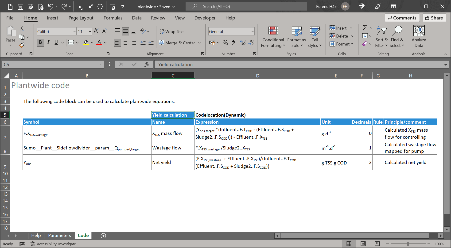
Building the plantwide code for this example consists of the following 3 steps (Figure 6):
- Calculate mass flow of waste TSS (F.XTSS,wastage in equation) from PWE Equation 1.
The wastage TSS mass flow is expressed from the equation using the target yield. The Influent..F.TCOD mass flow rate could be written as Pipe2..F.TCOD as Pipe2 is connected to the Influent process unit's output port. - Calculate target pumped flow dividing the mass flow by the waste TSS concentration.
The wastage flow is usually an input parameter in the waste flow divider, but to meet the target yield, it can be calculated as the target flow based on the waste TSS. Remember to use the full namespaced version. As it can be seen the Qpumped,target symbol (as in Process Code excel file) can contain the ‘,’ and it will be converted into ‘_’ automatically. - Calculate net yield
This step calculates the actual net yield which is equal to the target yield in algebraic direct control mode. If rows 7 and 8 would be deleted, the model would just use the wastage flow from the GUI input and simply calculate Yobs.
Note, that all the variables used on the Code sheet in an expression will have the value in their ‘in code’ unit. This means that in case the SUMO interface shows values in ‘SI’ or ‘US’ it might be different from the ‘in code’ unit system value. Always check for ‘in code’ units of the variable and use unit conversion if needed.
When saving the file, it must be placed to the autogenerated Project folder - it was opened from there. After saving and closing the Excel file, continue with your workflow. The compilation of the model starts after this point however when changing the plantwide file after the compilation is complete, rebuilding the model is necessary each time.
¶ Set parameters at input setup
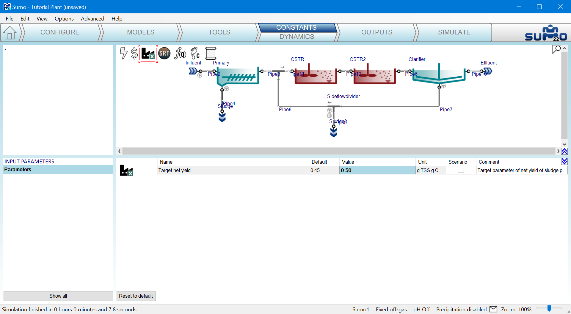
To reach the new parameters of the project, at input setup the Plantwide excel/Factory icon has to be selected. The bottom left panel lists the parameters added to the plantwide excel:
¶ Add variables to output setup
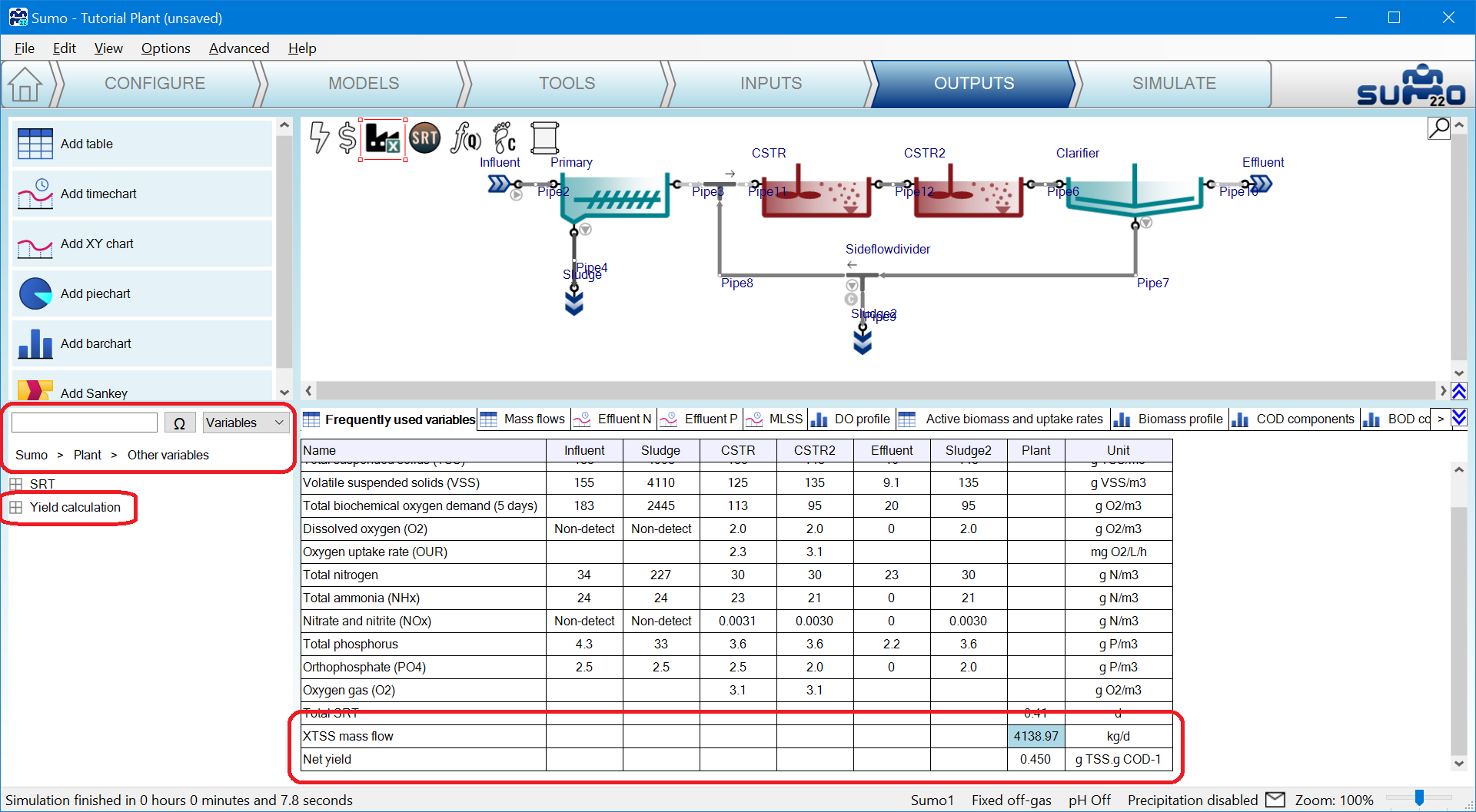
To reach the new variables of the project at output setup the Plantwide excel/Factory icon has to be selected. The bottom left panel lists the variables under Sumo|Plant|Other variables|Yield calculations added to the plantwide excel. Note the list name as it is the block header on the code sheet, see cell C5 on PWE Figure 8.
