
¶ 1 Introduction
This documentation contains the elements of the Sumo modeling language. Although it is not simple, once mastered, wonderful models can be created in a well-organized and documented fashion. From now on the modeling language will be referenced as SumoSlang.
¶ 1.1 What is SumoSlang?
SumoSlang is the modeling language used in the Sumo process modeling software. It was developed with modeling very large systems in mind: containing process units and process models. It was developed also with engineers in mind: write your equations in a familiar environment namely Microsoft Excel.
The naming, organization of tables and their content on various Excel worksheets and the keywords used is known as SumoSlang. Some of the main features of the language are:
- assignment oriented,
- assignment: only one variable is allowed at the left-hand side of the equation,
- formatted equation: symbols with arbitrary formatting (subscript, superscript, Greek characters) are allowed on both sides of the equation, - it is easy to comment and add notes,
- documentation and code are at the same place,
- algebraic calculations,
- dynamic calculations
¶ 2 Structure
The Sumo process modeling software contains a standard library of process code. The elements of this library are process code files in the above-mentioned Excel document format which represents the source code of the library. There are three process code types:
- general settings—with the fixed file name
systemcode.xlsx - process model—with arbitrary file name, e.g.
Sumo1.xlsm(the model files usually contain macros for validation, hence the .xlsm extension) - process unit—with arbitrary file name, e.g.
CSTR with diffused aeration and input DO.xlsx
SumoSlang is processed by the so-called Sumo Model Translator (SMT) first, which understands SumoSlang and converts it to an intermediate XML format for further processing. This documentation will discuss the SumoSlang features and rules from the SMT point of view. The graphical user interface of the Sumo modeling software may impose other requirements on the process code e.g. various worksheets containing irrelevant data for the SMT.
The standard library source code is placed in a specific folder structure shown on the following picture, where the Sumo install folder is open in Windows Explorer.
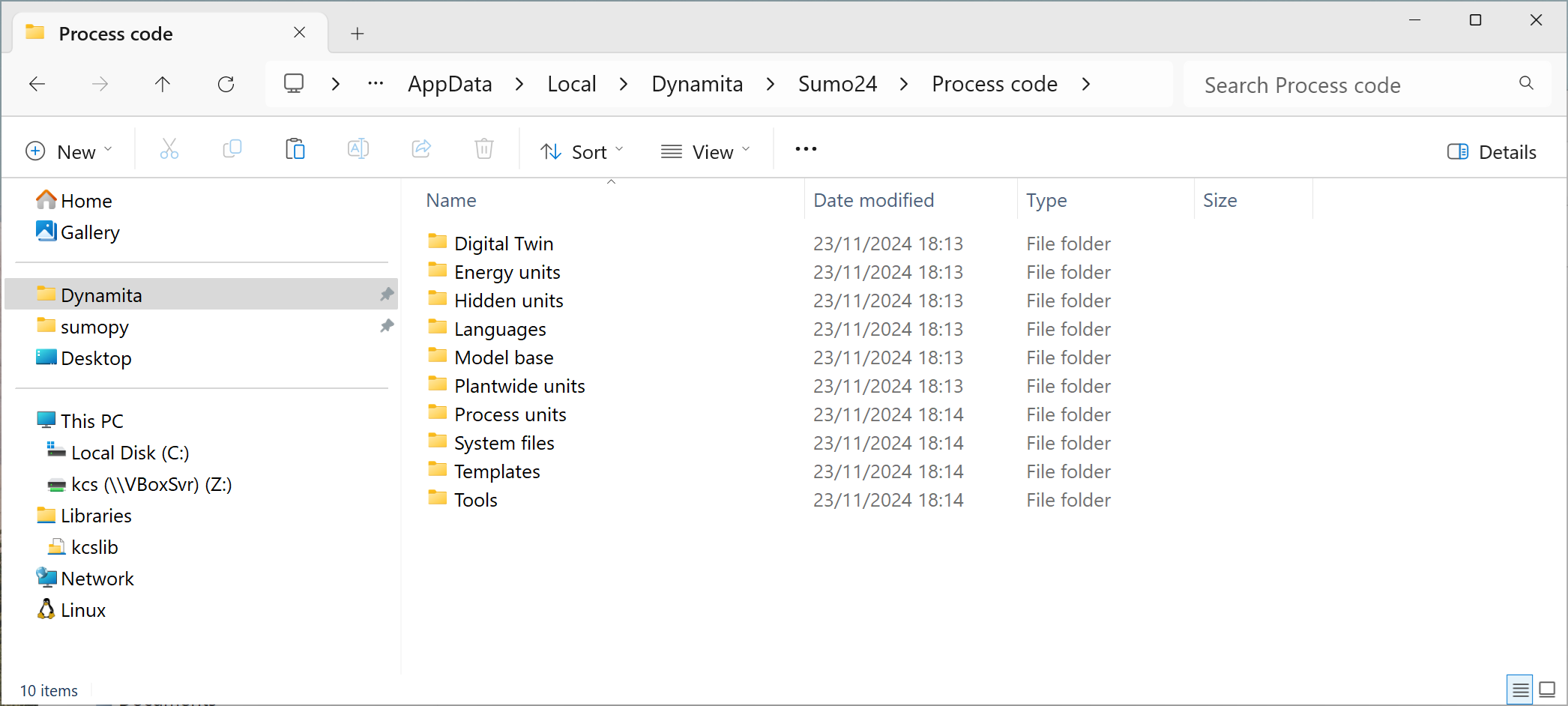
Figure 1. - Sumo process code structure
The SMT will search for process code files (settings, models, process units) specified at the beginning of the chapter in the directories listed above. It is considered a good practice not to modify the standard library, but place user code in the My Process Code folder which has the same inner structure as Process Code.
The following sections will explain the structure of the different process code files, what are their mandatory elements and what can be freely chosen by process code authors.
¶ 2.1 General settings
Sumo settings are stored in a special Excel file named systemcode.xlsx. The name of this file is mandatory.
Figure 2 shows the first worksheet of the system code with other worksheets expected by the SMT highlighted in red:
- System settings—various system wide settings and constants
- Functions—function declarations recognized by the SMT
- Constants—scientific constants used in calculations
- Sumoconv—dictionary of special (Greek) character conversions to C++ code
- Species—dictionary of chemical species
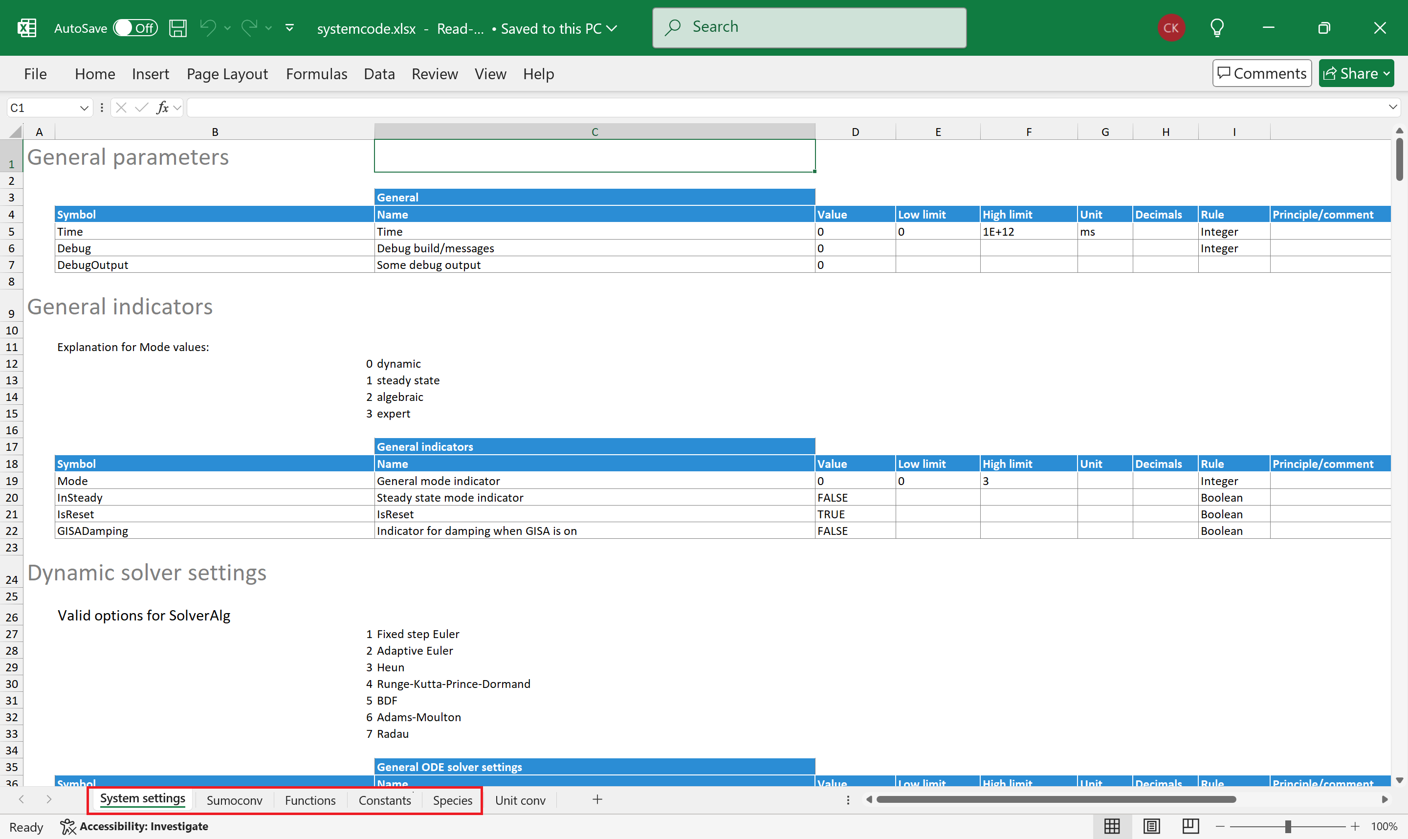
Figure 2. - The systemcode.xlsx file containing systemwide settings. The worksheets highlighted in red are expected by the SMT.
¶ 2.2 Process model
The model files contain various scientific equations, matrices and parameter values used in simulations. Process units may reference one or more models; thus, the variables and equations of the included model(s) are available in process unit calculations.
Figure 3 shows a model file example with frequently used worksheets highlighted.
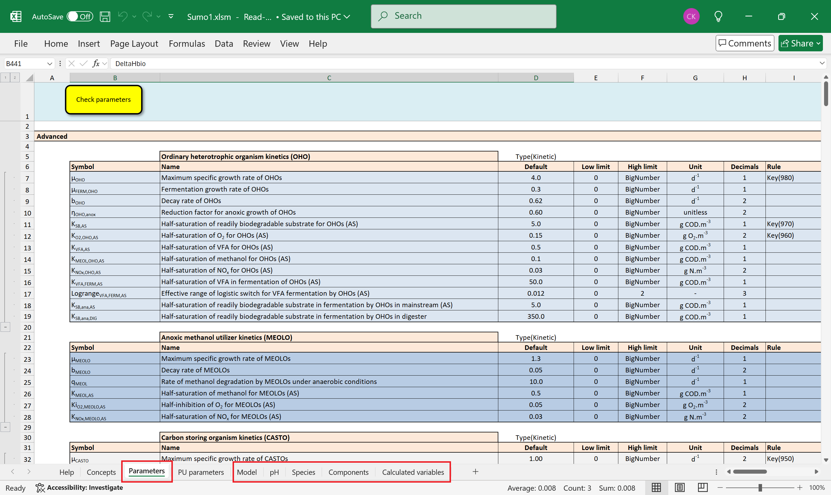
Figure 3. - Excel file containing model code. The worksheets highlighted in red are usually used in process unit calculations
Some of the worksheet names are mandatory, others are arbitrary. The mandatory names are expected by the SMT when a shorthand symbol is evaluated (see subsections of 5.1 Expandable symbols).
The fixed names are:
- Parameters—is a list of parameters having fixed numerical values used in calculations
- Species—a dictionary of equilibrium species used in pH calculations
- Components—contains state variables in dynamic systems, or model components in algebraic systems (e.g. chemical species that determine the chemical composition of the investigated solution: Ca2+, Mg2+, etc.)
- Calculated variables—contains equations calculating variables dependent on other variables
Other worksheets with arbitrary names are:
- Model—contains the so-called Gujer or kinetic matrix, which is a table used by process units to calculate biokinetic reactions.
- pH—contains all the information to calculate the equilibrium species in reactions that are considered during pH calculations
The model may contain other, user defined worksheets which can be referenced in process unit code. The referencing methods are discussed in section 5.1 Expandable symbols.
¶ 2.3 Process units
The process code contained in process units describe the behavior of bioreactors, flow elements separators and other modeled elements. As mentioned above the process units may “pull in” variables and equations from one or more model files and use them in their calculations.
The process units should be able to work with different models which means that they cannot reference models by name, but some other mechanism. See again section 5.1 Expandable symbols for more information.
Figure 4. shows the code of a process unit with the commonly used worksheets highlighted. The names of these worksheets are mandatory.
- Unit—a dictionary of attributes and component handlings valid in the process unit (see sections 5.2.1 Attributes and 5.2.2 Handlings)
- Parameters—contains the simulation parameters modifiable by the user in the Sumo process modeling software. These are valid only in the process unit, but model parameters can be “pulled in”.
- Code—contains the process code of the process unit grouped in so-called code locations (see section 3.2.1 Table)
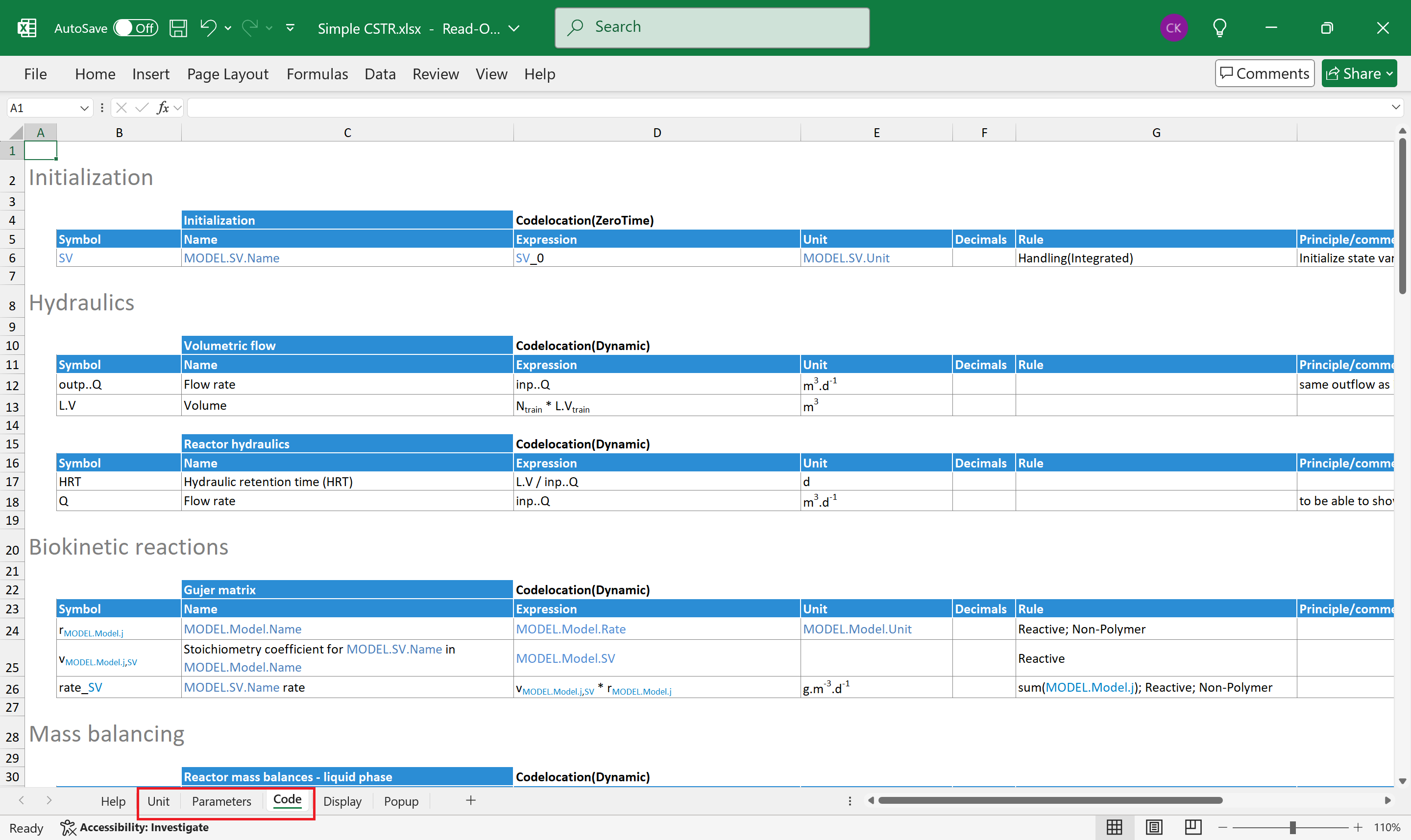
Figure 4. - Process unit file with the commonly used worksheets highlighted in red.
Other, optional worksheets useable by the SMT can be added to the process unit. These worksheets also have mandatory names, and they are the following:
- Components—it is like the Components in the model but valid only in the process unit. They may overwrite model components.
- Functions—it is like the Functions in the systemcode.xlsx but valid only in the process unit.
- Structure—is present in composite process units. Contains the list of components and connections between them, as well as connections to the outside world.
¶ 2.3.1 Composite process units
A process unit may consist of several subunits. The components are separate process units with their own process code files. Grouping them in a single process unit hides the internal complexity, the group behaving like a black box with few connections to the outside world.
The Structure worksheet introduced in the previous section contains this grouping information. Figure 5. shows an example of the Structure sheet of a composite unit.
Columns of the component table play an essential role in how the composite unit controls its components (see section 2.4 Process unit hierarchy).
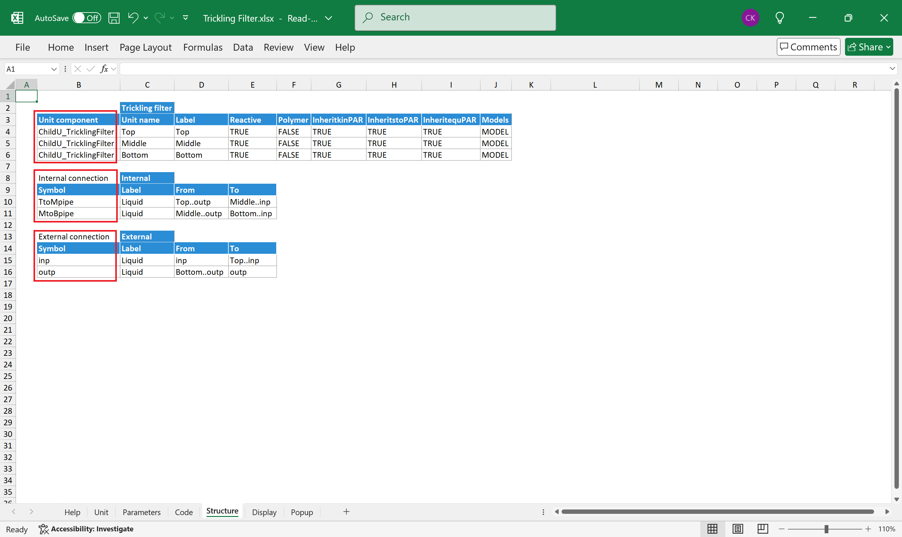
Figure 5. - Structure worksheet of a composite process unit showing three components, their internal connections and the external connections of the whole composite unit.
¶ 2.4 Process unit hierarchy
In Sumo software the modeled plant is organized in a process unit hierarchy. The root element is (an artificial) composite process unit which lists the participating process units as components. These process units may be simple or composite too.
In the previous section it was mentioned that composite process units (parents) control their components (children). This control is represented by passing so-called attributes, handlings and parameters from the parent to the children (see sections 5.2.1 Attributes and 5.2.2 Handlings).
The artificial root element is provided for the user by Sumo software to be able to set plantwide simulation properties and parameters. The Unit and Parameters worksheets of a process unit contain attributes, handlings and parameters valid in that process unit, but these values can be overwritten by the root element or by a parent composite unit (if the process unit is part of one).
The intention of overwriting can be declared in the columns of the component table present on the Structure sheet of the parent process unit. On Figure 5 the Unit component table has columns between Label and Models. Those are attribute names and the values in the different rows are passed to the corresponding process unit.
In a similar manner, columns after the Models column represent handling names and the values in the different rows are passed to the corresponding component (the example does not contain such columns).
Where a cell in a column is empty, no value is passed to the component unit thus the value defined in the component unit prevails.
Figure 6 shows the hierarchy of four modeled process units (PU1, PU2, PU3, PU4) where PU1 and PU4 are composite units consisting of two process units: PU1,1, PU1,2 and PU4,1, PU4,2 respectively. The example shows, on the left side of the hierarchy, how attributes and handling can be passed from parent to child, while the right side shows two methods for passing model parameters from parent to child.
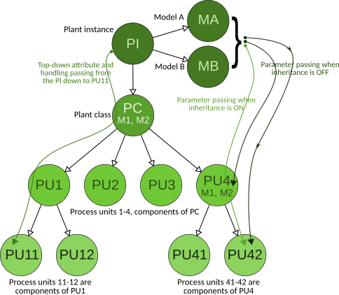
Figure 6. - Simple process unit hierarchy. The dashed line between the Root and the Model means that the Root is not the parent of the Model, only uses it.
Parameter passing has a special name in SumoSlang: parameter inheritance. It is explained in section 5.2.1 Attributes in more detail. Here it is enough that when inheritance is ON the parameters come from the parent of the process unit, otherwise from the model. The root process unit always takes its parameters from the model.
¶ 2.4.1 Plantwide code
Global settings and properties can be given in the so-called plantwide code file. This is provided by the Sumo software per modeled plant and it is not part of the process unit library accompanying the software.
One can think of the plantwide code as if the software would give access to some elements of the artificial root process unit. The plantwide code file looks like a normal process unit, it has Unit, Parameters and Code worksheets and the data given on these worksheets will be incorporated in the root element. However, the user cannot reach the Structure sheet of the root element through plantwide code.
Composite process units can reach parameters and other variables of their direct children by prefixing the variables with the child unit name like this:
ChildName..variable
The plantwide code is an exception at the moment of this reference rule. When a variable from a child unit (direct or deep in the hierarchy) is needed in plantwide calculations it should be qualified with its full namespace prefix (see chapter 7 Namespaces).
¶ 3 Process code layout
Figure 2 shows a worksheet containing typical process code. The process code rows are placed in neat tables which gives an organized look and feel to the code. The tables are separated by at least one blank row. Note that the pretty formatting and coloring of the tables does not influence how they are perceived by the SMT. For example, if the user would insert some text in cell B8, the SMT would include it in the first table. The tables contain the process code and anything outside of them is considered as comment and ignored.
¶ 3.1 Table structure
Every table should have a
- descriptor—a 3-segment cell range B3:D3 in the example mentioned above
- table type—cell B3, it can be empty or may contain one of the following keywords
- Array
- if block
- C++ code
- Newton-Raphson—used in model code on the Calculated variables worksheet
- Port, Attribute, Model, Handling—used on theUnitworksheet of process units
- SolverConfiguration—meant to replace Newton-Raphson table types in tandem with Equilibrium code locations (see 9 Advanced topics) - table name—cell C3, contains a meaningful grouping name of the table content
- table tag—cell D3, like table type it can be empty or may contain one of the following keywords
- Pure—used only on theFunctionsworksheet of system settings
- Type(arg)—used in model code (Parameters, pH, Calculated variables) for further grouping tables
- Codelocation(arg)—used on Code worksheet of process units. The argument may be one or more of the following keywords: ZeroTime, DataComm, Integrated, Equilibrium
- Scope(arg)—used onUnitworksheet of process units - header—the range B4:J4 in the example. The number of columns is arbitrary. Some of the column header names are fixed (e.g. Symbol, Name, Value, Rule) others are arbitrary.
- body—the code lines grouped in the table (the body can be empty). Its range is B5:J7 in the first table of the example.
- table type—cell B3, it can be empty or may contain one of the following keywords
¶ 3.1.1 Simple table
Usually, the range of a table is determined by the content of the Symbol column and the header row as shown on the following picture.
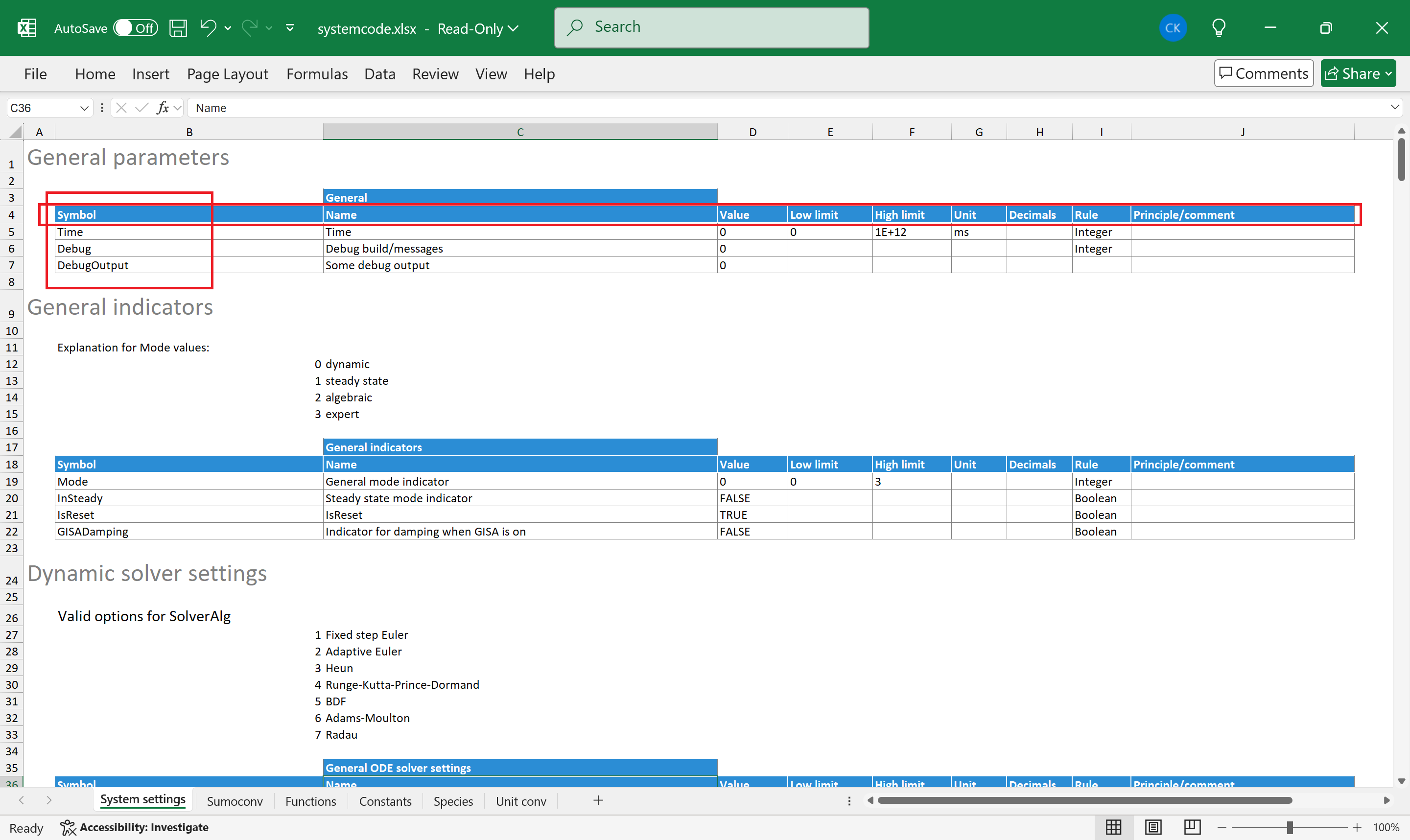
Figure 7. - Table boundaries.
The key elements like descriptor, header and body described in the previous section are determined relative to the Symbol cell. The table extends to the right and down while the Symbol row and column contain non-empty cells.
Some table types do not follow this structure but should comply to some different structure nevertheless. Such table types are the Array, if block and C++ code.
The rows of a code table represent assignments in the form of a = b, or more precisely a ← b (b goes to a). The left-hand side of the assignment is in the Symbol column of the table, while the right-hand side is in one of the Value or Default or Expression columns. In some cases, the Expression column may break down into several parts (see 3.1.2 Array).
¶ 3.1.2 Arrays
Arrays are fundamental in every programming language. In SumoSlang they can be specified in three ways. The first is a simple table containing a row with its symbol in array notation e.g. var[]. SumoSlang requires a so-called array rule in the Rule column of the array row, like [n], where n is the size of the array, and it is declared on the Parameters sheet of a process unit file. The examples were taken from the Layered SBR with calculated DO.xlsx.
Figure 8 shows an example of array size definition. On the Parameters worksheet the right-hand side of the assignments is contained in the Default or Value column.
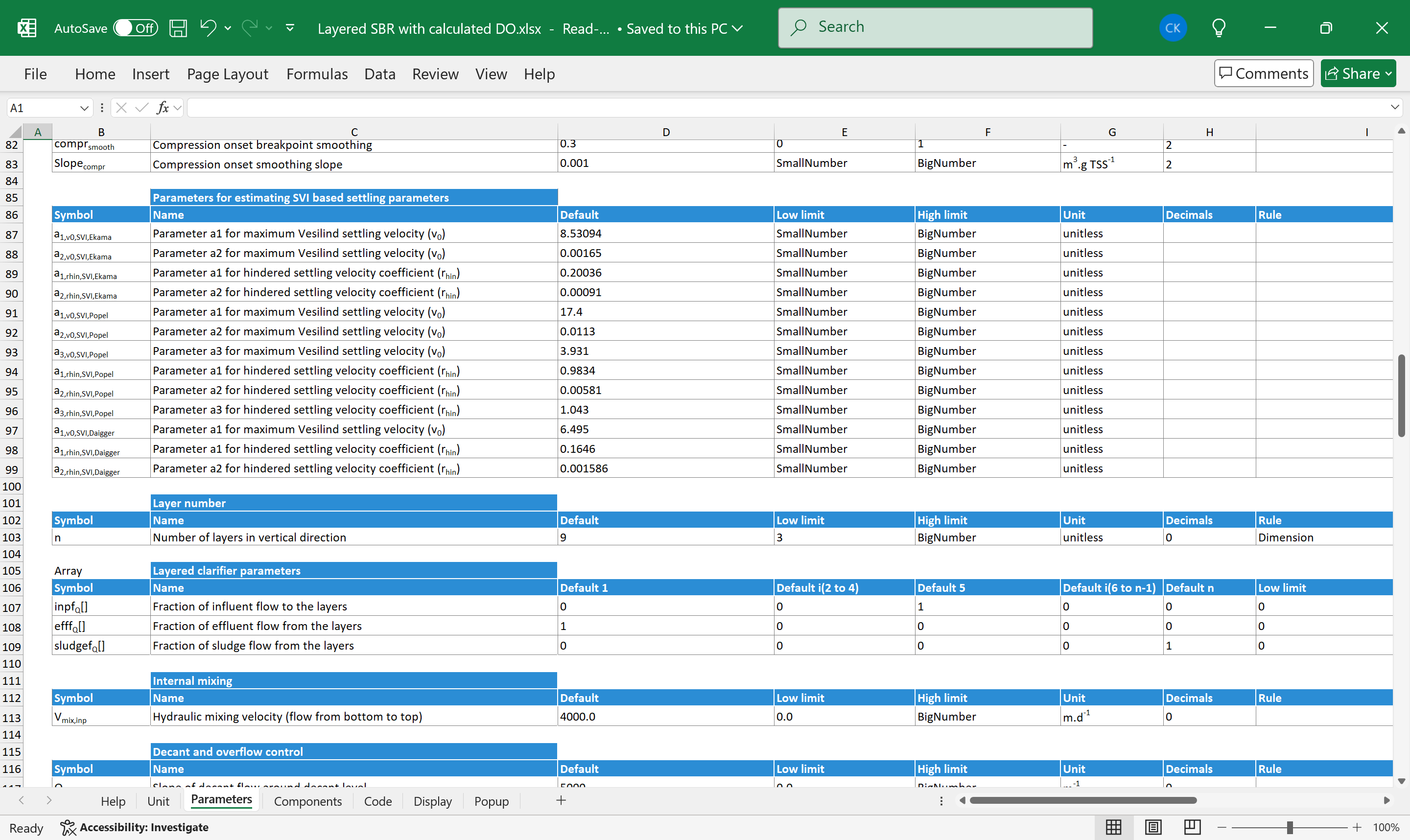
Figure 8. - Dimension type variable definition in row 103.
An array size definition requires a Dimension rule specifying that it is an array dimension type variable. It is worth mentioning that SumoSlang handles only one-dimensional, real number arrays for now.
Figure 9 shows an example of simple arrays in various code tables.
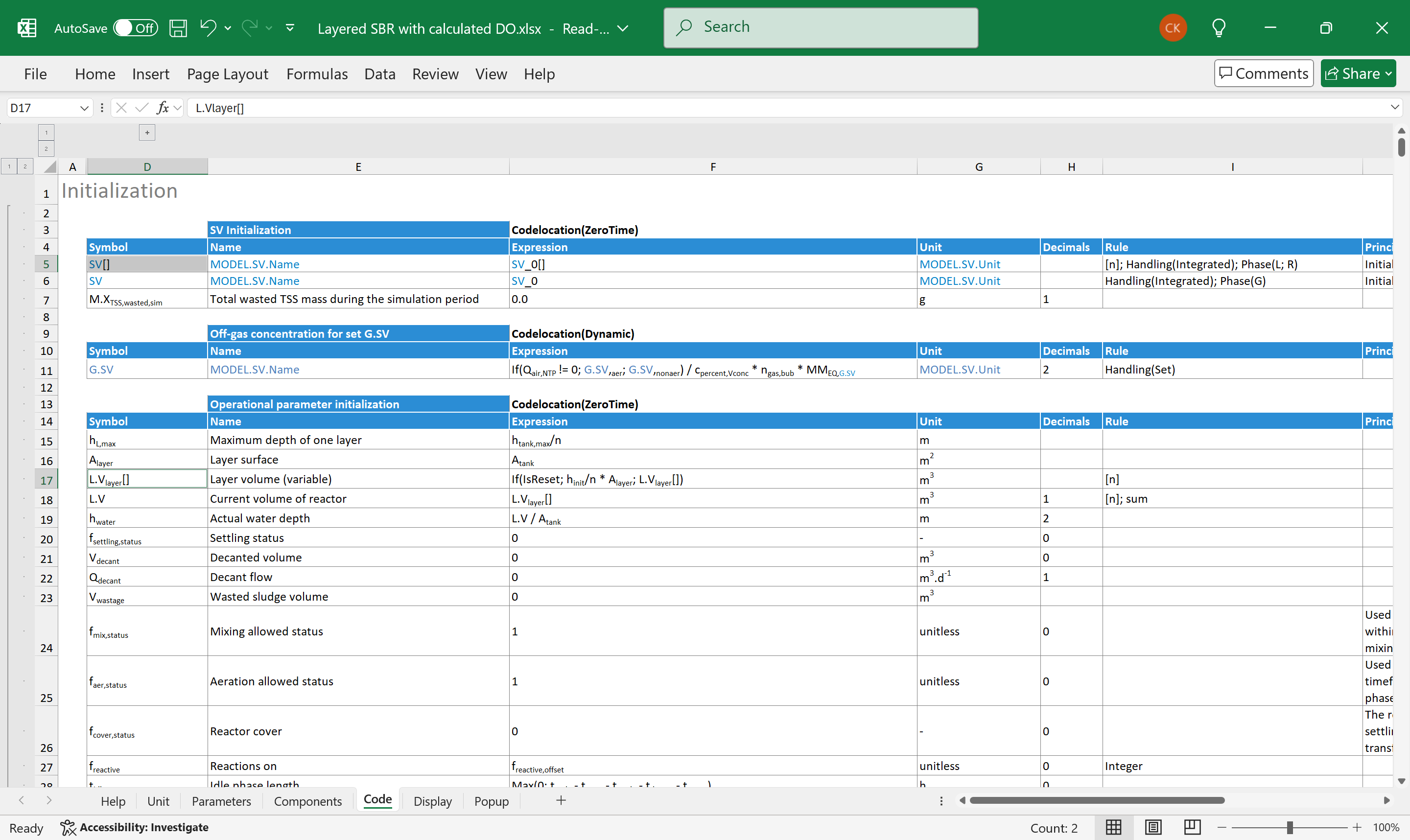
Figure 9 Array rows in two tables: rows 5, 17 contain arrays with their symbol ending in brackets and with [n] in their Rule column.
The SMT will unwind an array row to a loop where the elements of the array will be assigned to the right-hand side contained in the Expression column. In our example n is defined as 9 meaning that all arrays with rule [n] have 9 elements. Row 5 for example will be unwound as follows:
SV[1] = SV_0[1]
SV[2] = SV_0[2]
...
SV[9] = SV_0[9]
or more precisely to an equivalent loop. Note that the expression is also in array notation, i.e. ending in brackets.
The second option to define an array is to set the table type to Array in the table descriptor. The SMT is prepared that the Expression column may be broken in several parts. Figure 10 shows an example of this array type.