¶ SUMO OPC connectivity
We assume that you have an OPC UA server installed and set up correctly. Setting up the server, or connecting it to real plant hardware, is out of the scope of this document.
SUMO can connect to an OPC UA server in two ways:
- from the graphical user interface
- from the SUMO PythonAPI using the
dmqclient.pymodule
It is important to mentions that the OPC features of SUMO are available only in Windows at the moment. The GUI connectivity will remain Windows only, but Python connectivity may be available later on Linux as well.
¶ Connection from the SUMO application
DISCLAIMER:
THE OPC DASHBOARD IN SUMO IS ONLY FOR TESTING AND VARIABLE MAPPING PURPOSES!
You meet the OPC connection feature for the first time in the SUMO application, in the Advanced/OPC Dashboard menu.
Before connecting to our OPC UA server you need to prepare a few things:
- Create a few, SUMO related, data tags in the OPC UA server (using its client application provided by the server developer company).
- Set up the connection in the
sumo.inifile.
¶ SUMO GUI specific data tags
You will need to create the following new data tags in the OPC UA server:
FastModeMultiplier- speeds up a real time simulation (default is 0)MasterSumo- specifies that Sumo is the time provider (default is false, or 0)SumoContinue- specifies a flag to continue a stuck simulation (default is false, or 0)
In the following example we will use the KEPServerEX OPC UA server, to show how to set up the required data tags. You can choose other OPC server solutions as well.
In the KEPServerEX configuration tool add a new channel named Channel1 if it's not there already. When creating the channel, you should be able to use a so called driver, which is compatible with your plant hardware. In the example we chose Simulator, which is good for testing purposes:
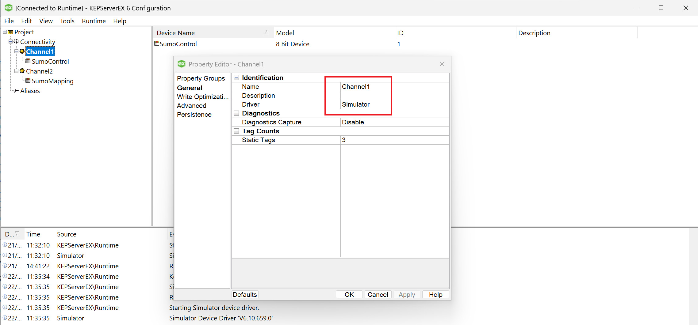
Figure 1 - Channel1 properties
Add a new device under Channel1 named SumoControl with the following properties:
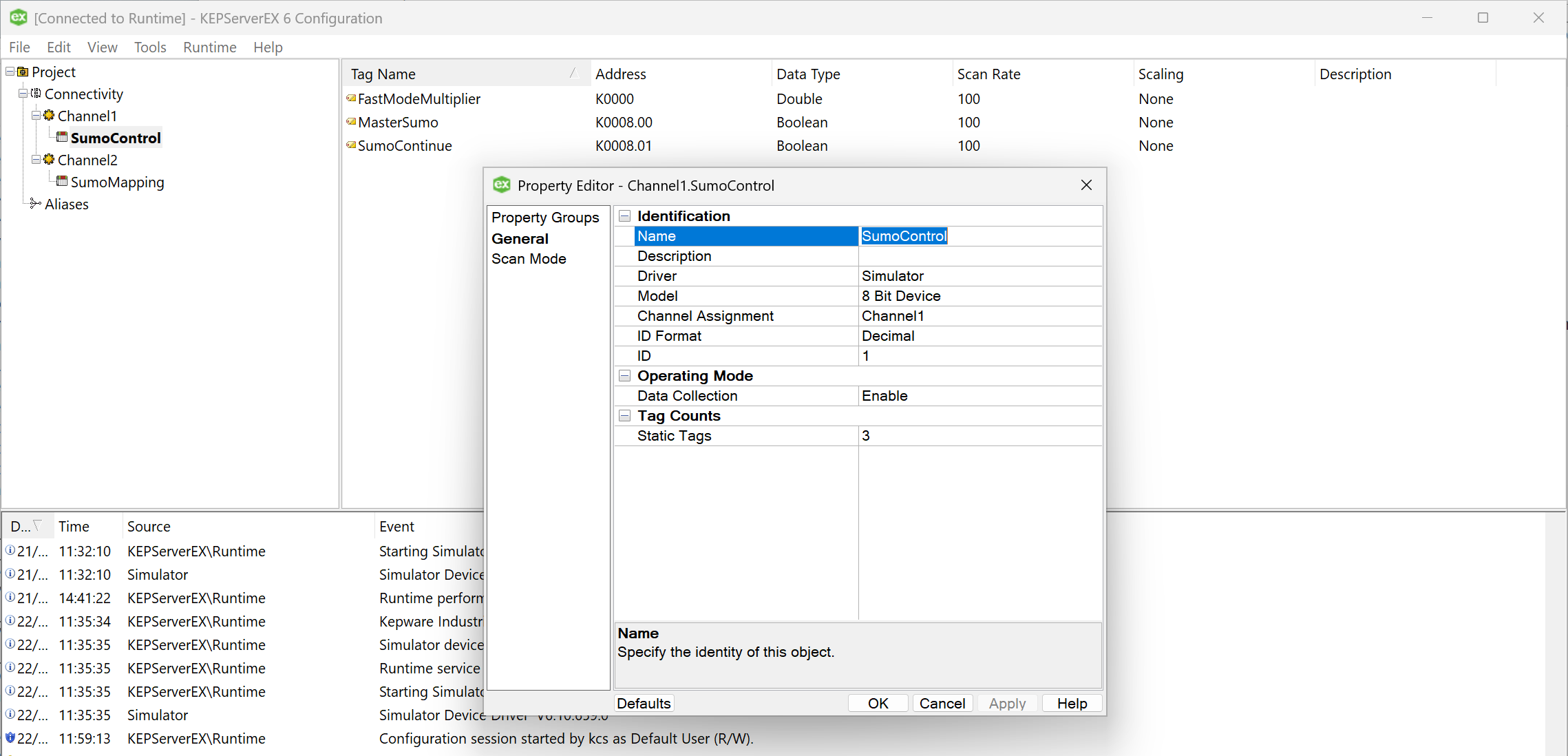
Figure 2 - SumoControl device properties
Add the required data tags under the SumoControl device, which will look like the following:
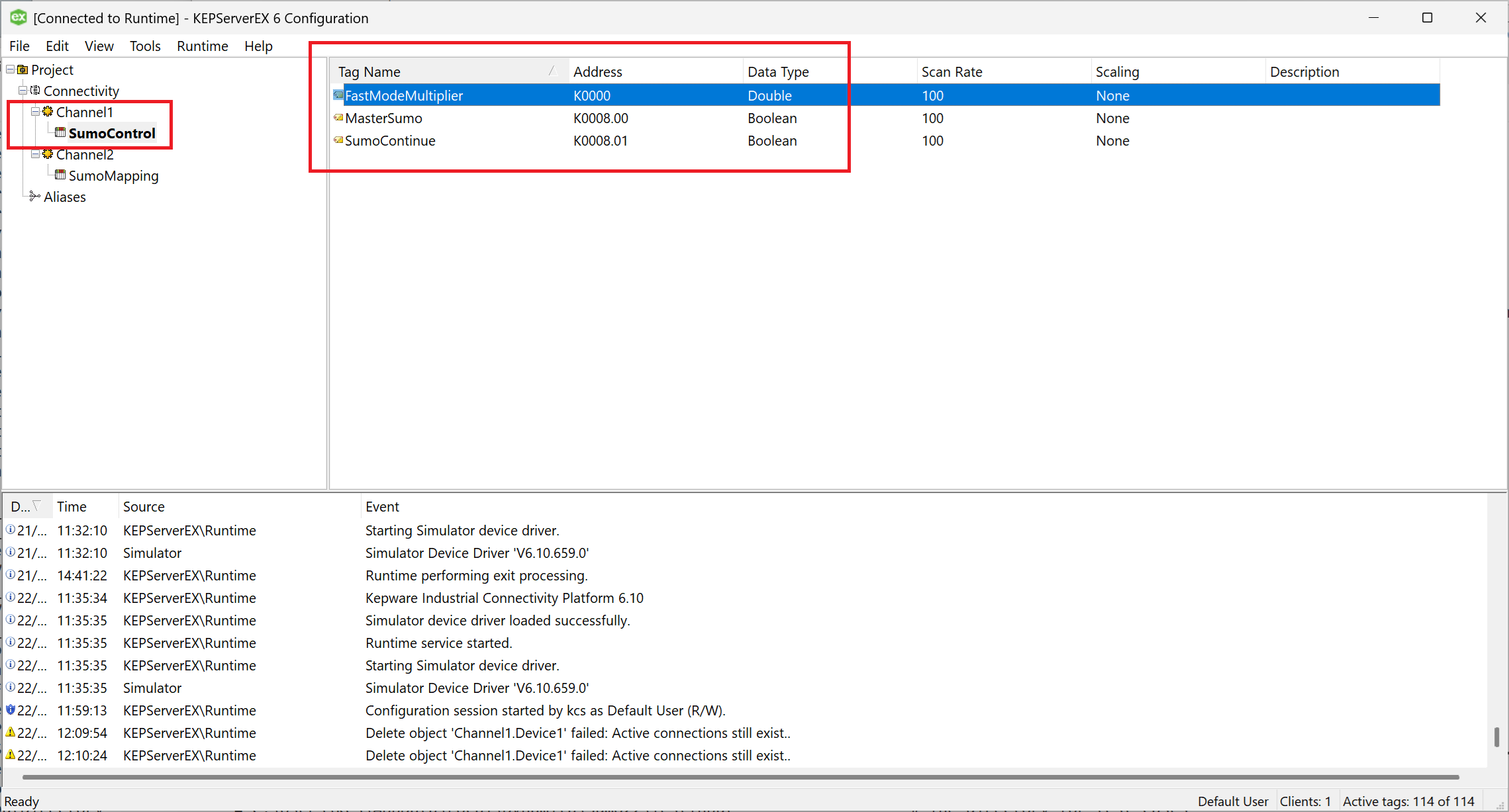
Figure 3 - SUMO data tags in the KEPServerEX configuration tool
¶ Setting up OPC connectivity for SUMO
You need to add a few entries in the sumo.ini file, usually located in the user's AppData/Roaming/Dynamita/Sumo24 folder (it may vary depending on how SUMO was installed). The required entries are:
OPC_UA_Url                          = opc.tcp://localhost:49320
OPC_FastModeMultiplier              = Channel1.SumoControl.FastModeMultiplier
OPC_MasterSumo                      = Channel1.SumoControl.MasterSumo
OPC_SumoContinue                    = Channel1.SumoControl.SumoContinue
OPC_Time                            = Server.ServerStatus.CurrentTime
The OPC_UA_Url entry contains the address of the OPC UA server. SUMO will fill this address into the OPC Dashboard.
The next three entries are the data tags introduced in the previous section. You can use different structure in the OPC UA server, you don't have to follow this setup. You will need to know, however, what is the full name of the data tag, and specify it in the sumo.ini.
In KEPServerEX you can see the full name in the title bar of the data tag property, as shown in the following picture:
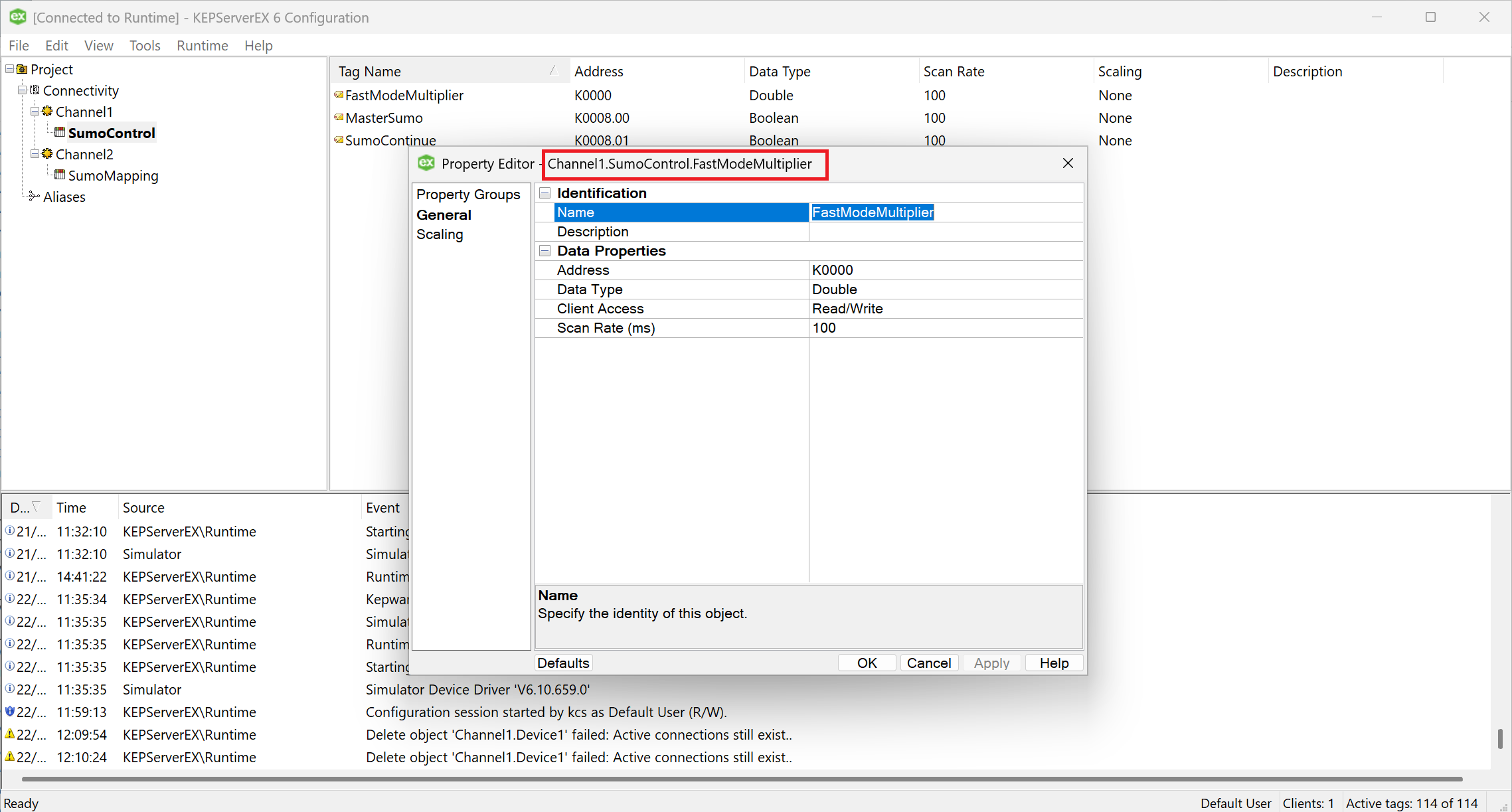
Figure 4 - Data tag full name in the Properties title bar
Finally, the last entry is the OPC_Time which should be the current time system data tag. It is present in most OPC UA server implementations and it is named Server.ServerStatus.CurrentTime. If your server doesn't have this system tag, please consult with Dynamita at support@dynamita.com.
The system time is important for real time synchronization of SUMO simulations.
¶ Connecting to the server from SUMO
After the sumo.ini preparation you can test the connection from the SUMO application. You will need a compiled project to be able to start the OPC Dashboard. Let's open the Tutorial plant example and open the OPC Dashboard from the Advanced menu:
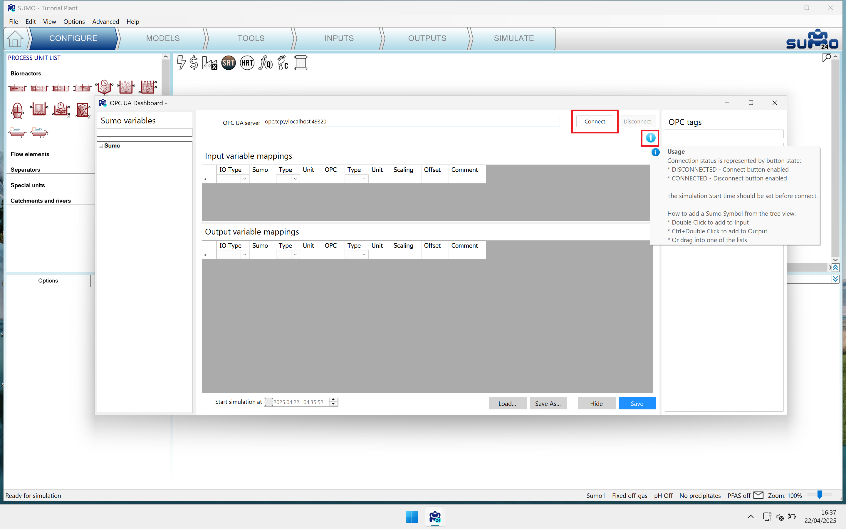
Figure 5 - OPC Dashboard; hover the mouse pointer over the i icon to get a help popup
You can connect to the OPC UA server accessible at the specified address, by pressing the Connect button. If the connection was successful, you will see all data tags present in the server listed on the right side of the dashboard, like in the following picture:
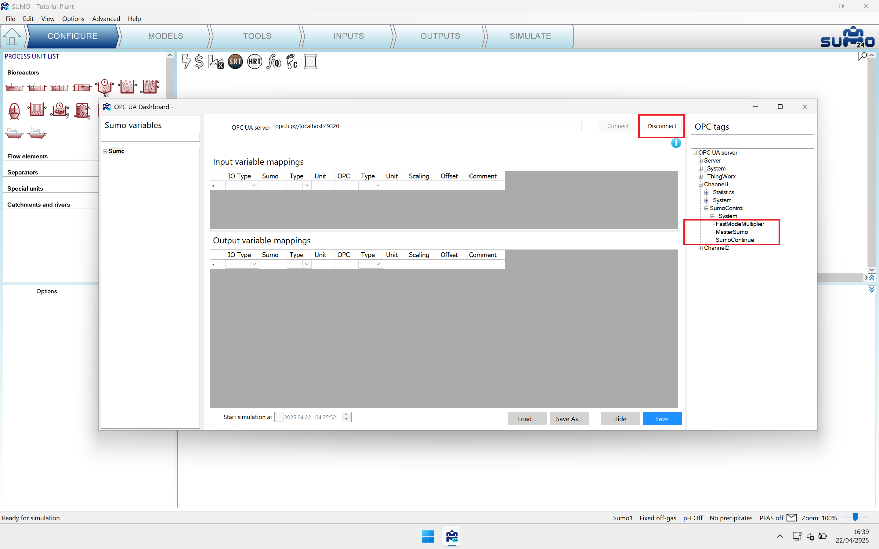
Figure 6 - Connection to the specified server was successful; the SUMO application specific tags are on the right side
You can disconnect from the OPC UA server by pressing the Disconnect button, or by closing SUMO; it will close automatically an open connection.
¶ Setting up a real time simulation
You will need a list of input parameters and output variables which will be connected to data tags in the OPC server.
For testing purposes you can select the influent flow as input parameter, and the effluent total phosphorus as output variable. As you could notice, we refer to SUMO input data as parameters, and output data as variables. In SUMO we can modify only parameter type data from outside.
Beside testing the connection to the server, another important feature of the dashboard is to create data mapping between SUMO and the OPC UA server. The process is like the following:
- select SUMO data symbols from the left panel and drag it to the input or output list
- select an OPC data tag from the right panel and drag it to the proper row of the input or output list
- delete a row, if needed, by pressing the Del key on the keyboard on the row you would like to delete
- repeat dragging and dropping symbols from SUMO (left) and the OPC UA server (right)
- save the mapping by pressing the
Savebutton. It will be saved into the project folder, which means that you will need to save the SUMO project as well after the mapping is finished. You can save the mapping outside of the project folder. If you choose so, the mapping will be available for other SUMO projects as well. The default behaviour is to save to the project folder (please remember that the project folder is temporary).
You will need to prepare data tags in the OPC server for the parameters and variables you would like to map to SUMO symbols. In the exemple we introduced the Plant_Q (full name is Channel2.SumoMapping.Plant_Q) and Plant_TP (full name is Channel2.SumoMapping.Plant_TP) in the OPC server.
Let's drag the Q parameter (full name is Sumo__Plant__Influent__param__Q) to the input table, then Plant_Q from the right side to the same row. The dashboard will auto-fill the full name into the table.
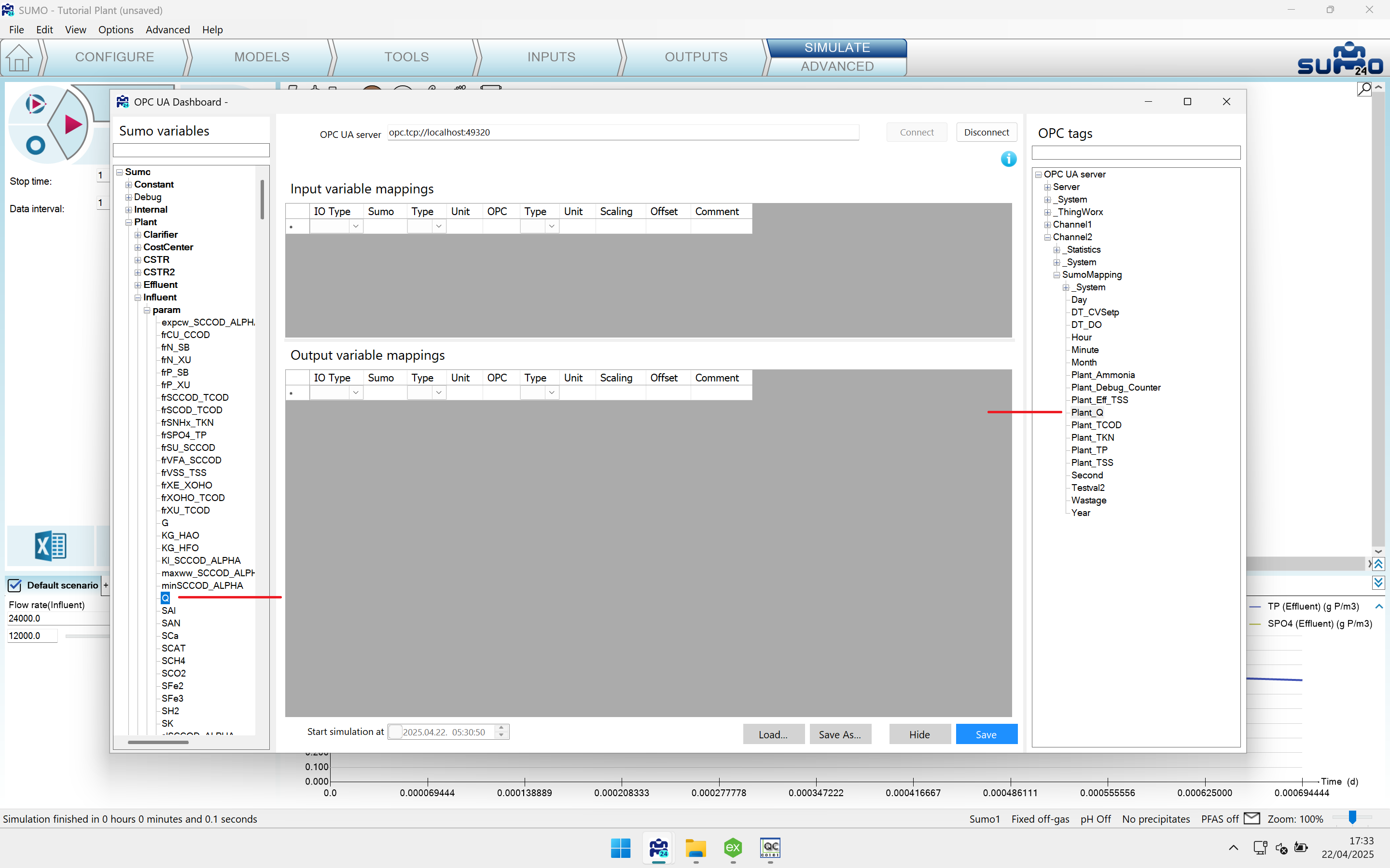
Figure 7 - Find Q under the Influent/param node, and Plant_Q under SumoMapping
Then let's drag the TP symbol (full name is Sumo__Plant__Effluent__TP) to the output table, then Plant_TP from the right side to the same row.
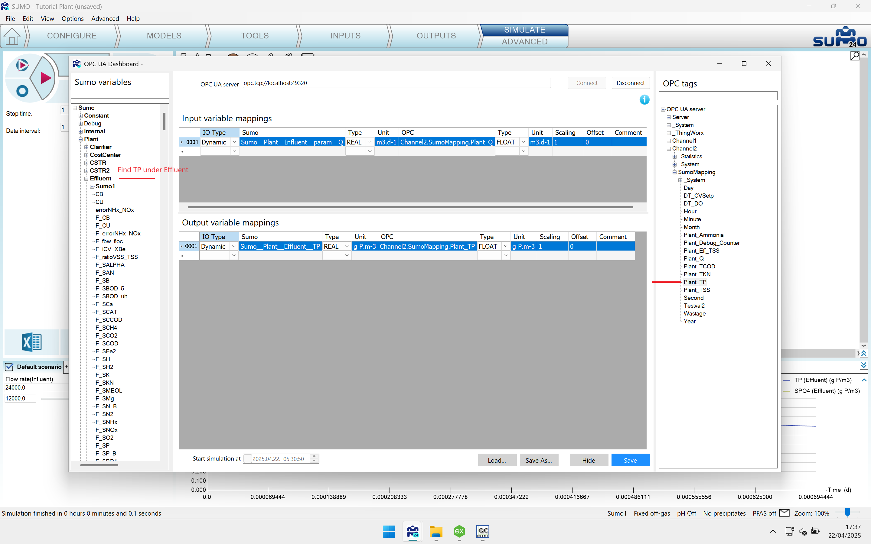
Figure 8 - Find TP under the Effluent node, and Plant_TP under SumoMapping
Save the mapping by pressing Save, then hide the dashboard with the Hide button.
¶ Running the simulation in real time
After the mapping was set up we can run the simulation in real time. The condition for this is to be connected to the OPC UA server. If you disconnect from the server, the simulation will run at full speed. Again, the OPC Dashboard is for testing the connection and create mapping between SUMO symbols and OPC data tags.
We change the StopTime from the default one day to one minute, and the DataComm to 5 seconds. This is required to see data changes at a meaningful time interval (5s) and the simulation doesn't run "forever", just 1m in real time.
Also, we add a new table containing the input parameter Influent Q and the output variable Effluent TP. This way we can test that parameter values indeed come from, and output variables are written to the OPC UA server.
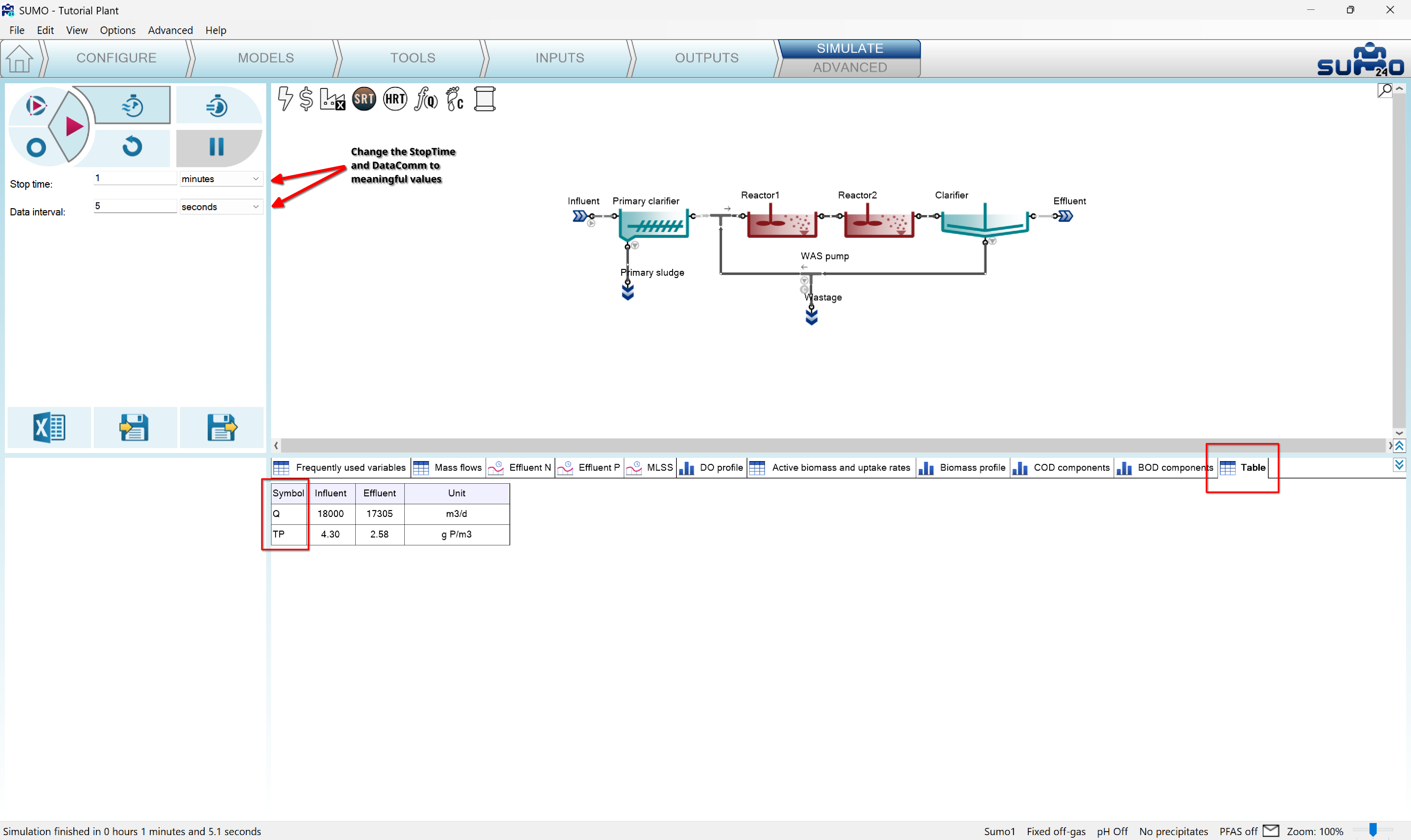
Figure 9 - Results of a real time simulation. We changed the influent flow to 18000 m3/d in the OPC UA server
The effluent TP is written to the OPC UA server as we can see in the Quick Client Tool started from the servers configuration application (Tools menu). We change the Plant_Q mapped to the effluent Q in our mapping file. The Plant_TP data tag will be updated from SUMO to the effluent TP value as the following picture shows:
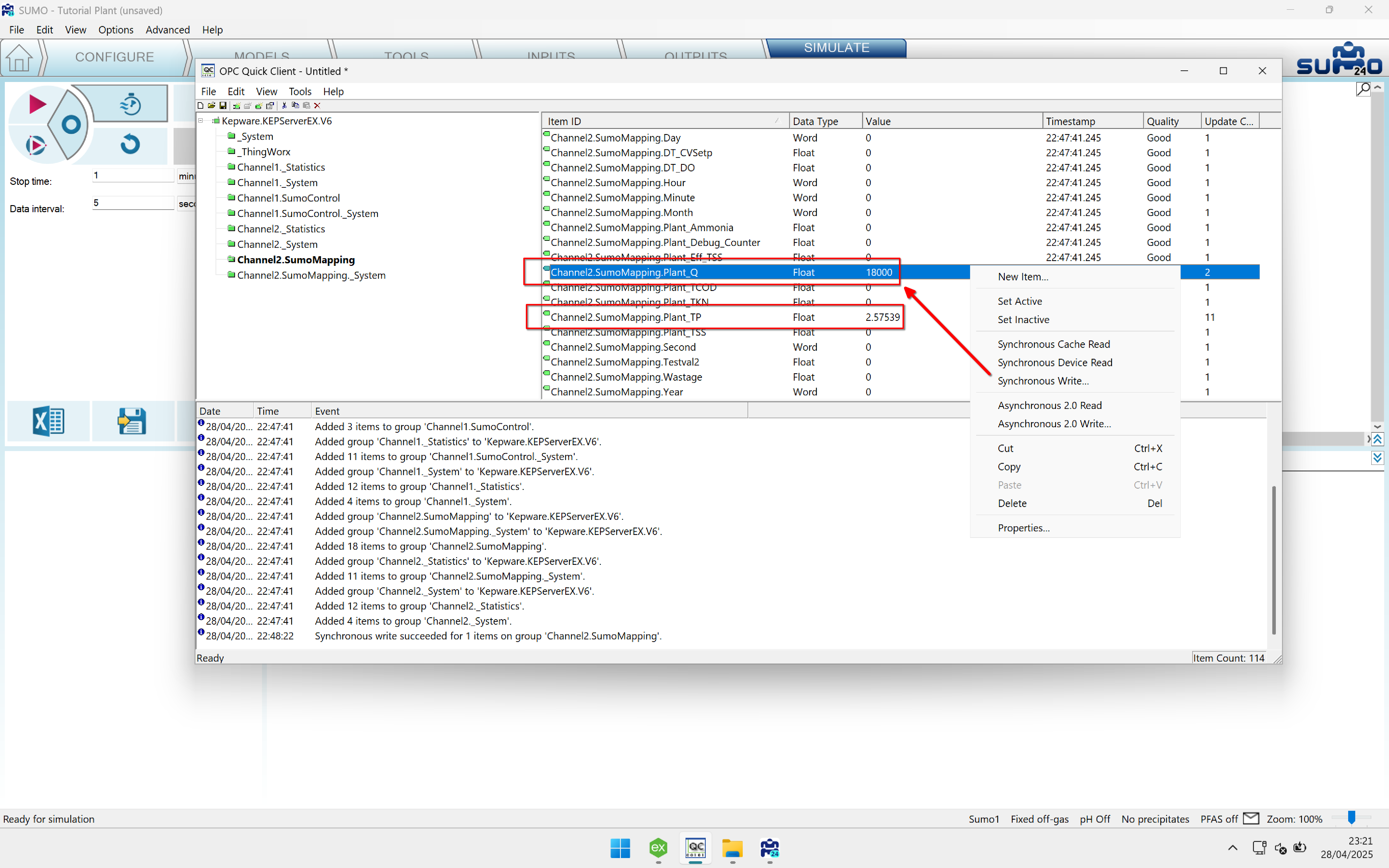
Figure 10 - Updating and checking data tags in the Quick Client Tool of the OPC UA server
When you start the simulation, you will notice that the data is updated at every 5 seconds and the simulation takes 1m + 5s to run (we wait for the last DataComm).
¶ Connection from the Python API
To learn more about the Python modules of DTT please study our DTT guide.
To learn about setting up a Python development environment for SUMO please refer to our guide.
After installing the DTT addon the SUMO installation folder will contain a PythonAPI subfolder, which contains the required SUMO modules used in our example.
The example will run the MLE-demo.sumo project, and process the mapping.csv file created with the OPC Dashboard. Processing the mapping means that input parameters will be read from the OPC server and the output variables will be written to the OPC server.
In the example we only write the output variables to the OPC server, no reading is performed. The source code is the following:
import dynamita.dtcontrol as dtcontrol
import dynamita.tool as dtool
import dynamita.dmqclient as DMQ
import time
import os

CURRENT_WORKING_DIR = os.getcwd()
SUMO_PROJECT = os.path.join(CURRENT_WORKING_DIR, "MLE-demo.sumo")
SUMO_STOPTIME = "1minute"
SUMO_DATACOM = "5second"
SUMO_STATE = os.path.join(CURRENT_WORKING_DIR, "sumo_state.xml")
OPC_SERVER_ADDRESS = "opc.tcp://localhost:49320"
OPC_CONFIG = os.path.join(CURRENT_WORKING_DIR, "Sumo.Config.xml")
OPC_MAPPING = os.path.join(CURRENT_WORKING_DIR, "mapping.csv")
TIME_TAG = "_System._Time_Second"
TIME_TICKS = 5
SIM_STEP = TIME_TICKS*dtool.sec
OPC_FREQ : float = 0.1

def sumo_to_opc(dtc):
    if dtc.GUI.is_running() :
        dtc.GUI.core_command_sync(f'save "{SUMO_STATE}"', "530045")
        data = dtool.read_sumocore_xml(SUMO_STATE)
        dtc.OPC.write_mapped_variables(dtc.OPCMapping, lambda x: x.io_type == "Dynamic" and x.io == "O", data)

def main():
    dtc = dtcontrol.DTControl()
    dtc.start_Sumo_GUI(SUMO_PROJECT, SUMO_STOPTIME, SUMO_DATACOM)
    dtc.OPC = DMQ.OPCClient(OPC_SERVER_ADDRESS, OPC_CONFIG)

    dtc.Tick_OPCTag = TIME_TAG
    dtc.Tick_TickToStep = TIME_TICKS
    dtc.SimulationStep = SIM_STEP
    dtc.Tick_CheckFrequency = OPC_FREQ

    dtc.OPCMapping = dtool.read_opc_mapping_csv(f"{OPC_MAPPING}")
    dtc.GUI.onstart(f"load \"{SUMO_STATE}\"; maptoic; set Sumo__LimitTime 1;")
    dtc.Tasks = [dtcontrol.DTTask(action=sumo_to_opc, starttime=TIME_TICKS, looptime=TIME_TICKS)]

    dtc.run()
    dtool.log_print("GUI closed")

main()
¶ Explanation
We start with importing the required modules. The SUMO modules are:
- dtcontrol - is responsible for GUI operations (starting SUMO, sending commands, pushing buttons etc.)
- dmqclient - is responsible for communication with an OPC server
- tool - contains various helper functions like data conversion, file operations etc.
After the imports we define a bunch of constants required by the SUMO modules. The meaning of most constants is straightforward, some need clarification:
TIME_TAG- the seconds component of the system time of the OPC server. It is a system data tag of the server.TIME_TICKS- the time in seconds to wait until the simulation advances. Until this time the simulation is stopped.SIM_STEP- the time in seconds to advance the simulation. In our case it is the same asTIME_TICKS.OPC_FREQ- how often (in seconds) the dtcontrol polls theTIME_TAGfrom the OPC server
In the example the simulation starts at 0s, the dtcontrol waits 5 real time seconds and advances the simulation to the 5th second in simulation time then to 10s, 15s etc.
Row 20 contains a call-back function passed later as a task to the dtcontrol, which will call it at every TIME_TICK.
Row 26 contains the main function. In it we create the dtcontrol object named dtc. With it we start the GUI in row 28, and pass the project name, stop time, and DataComm interval.
In row 29 we create an OPC connection object , and pass the server address and the configuration XML file.
Rows 31-34 we pass the constants to the dtcontrol. In row 36 we read the mapping file and pass it to the dtcontrol.
In row 37 we specify a core command to the GUI, then in row 38 we set up the task to be executed at the given time interval.
Finally we start the dtcontrol in row 40.
In row 22 of the call-back function we send a synchronous core command to the GUI (meaning we wait until it's finished) to save the state of the simulation. Then we read the state in a variable which will be used to search for the values of the output variables specified in the mapping file.
In row 24 we write the output variables to the OPC server.
The Python script will stop when we close the SUMO application (GUI).