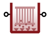
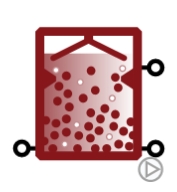
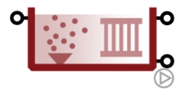
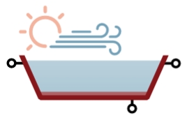
¶ Introduction
The following page gives list of the available process units in Sumo with a short description of their features.
¶ Process units
¶ Bioreactors
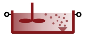
¶ CSTR
|
|
|
Continuously Stirred Tank Reactor with constant volume and ideally mixed concentration. |
|---|
Sumo offers two types of CSTRs: mainstream (with kinetic parameters preset for the liquid train) and sidestream (adapted to suit better for sludge train applications). The CSTR can also be switched to be non-reactive for specific modeling purposes. There are further options available regarding the aeration process:
Aeration options:
- diffused (with various built-in diffuser system specifications)
- mechanical
Dissolved oxygen handling:
- input DO (air flow requirement is calculated based on proper gas transfer)
- calculated DO (DO is calculated based on input air flow and proper gas transfer description)
- fixed DO (DO is fixed, without accounting for dynamics, while theoretical required airflow is calculated with the built-in aeration model)
Alpha factor options:
- predicted alpha (based on a correlation with TSS, therefore dynamically changing)
- input alpha (user-provided fixed value)
A simplified CSTR model is available for Museum models.
¶ PFR segment
|
|
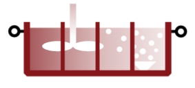
Plug Flow Reactor with constant volume and ideally mixed concentration in the individual segments. |
|---|
This type of bioreactor is available for mainstream applications and can be used to simplify the layout by representing a number of CSTRs connected in series. The aeration related options are the same as for CSTRs (except for mechanical aeration, which is not available). Influent or RAS split, as well as internal recirculation between the segments is not available in this model (for such applications, use the PFR process unit instead).
¶ PFR
|
|
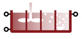
Plug Flow Reactor with constant volume and ideally mixed concentration in the individual segments, with influent/RAS split and internal recycle. |
|---|
This type of bioreactor is available for both mainstream and sidestream applications and can be used to simplify the layout by representing a number of CSTRs connected in series. In addition to the basic PFR segment model, this bioreactor can be configured for step feed (influent split), multiple internal recirculation pathways, as well as RAS split from the individual segments. The aeration related options are the same as for CSTRs (except for mechanical aeration, which is not available).
¶ HPO
|
|
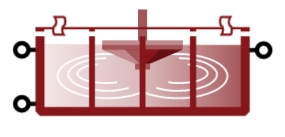
Plug Flow Reactor aerated using high purity oxygen, with step feed option. |
|---|
This model represents a series of closed mainstream CSTRs mechanically aerated with high purity oxygen. Influent split is available for modeling step feed, RAS split and internal recycling are not offered. Aeration related options regarding DO handling and alpha factor are alike to CSTRs.
¶ SBR
|
|
|
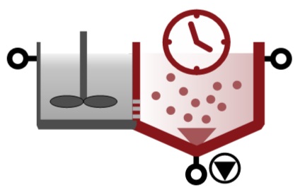
Sequencing Batch Reactor with various setup possibilities regarding the cycle of timed phases and tank structure for settling. |
|---|
The SBR reactor is available for both mainstream and sidestream applications and can be set up to represent different configurations, such as:
Typical SBR:
Featuring a fixed order of timed phases such as reaction, settling, decanting and wasting (idle phase is available as well). The tank is considered ideally mixed in the reaction phase. Decanting and sludge wasted is calculated with TSS concentration as setpoint.
- with calculated DO: DO is calculated based on input air flow and proper gas transfer
- with input DO: DO is set and input air flow requirement is calculated based on proper gas transfer description
- with fixed DO: DO is fixed, without accounting for dynamics, while theoretical required airflow is calculated with the built-in aeration model
Flexible SBR:
Featuring a flexible order of timed phases such as reaction, settling, decanting and wasting; based on user setup. The tank is considered ideally mixed in the reaction phase. Decanting and sludge wasted is calculated with TSS concentration as setpoint. Bottom feed cycle is possible.
- with calculated DO: DO is calculated based on input air flow and proper gas transfer
- With input DO: DO is set and input air flow requirement is calculated based on proper gas transfer description
- with fixed DO: DO is fixed, without accounting for dynamics, while theoretical required airflow is calculated with the built-in aeration model
Layered SBR with calculated DO:
Multiple layered tanks where mixing, settling and aeration is calculated according to the phase of the cycle. The settling model is identical to the 1D layered clarifier model. Available for typical and flexible cycle configurations as well but restricted to calculated DO handling.
Manual SBR:
In opposite to the Typical or Flexible SBR logic, in this case the operational logic is set up with dynamic tables to identify the different phases of operation. Another use case is the variable phase logic implementation using plantwide excel code. Available in both simple phase separation and layered flux model versions.
- with calculated DO: DO is calculated based on input air flow and proper gas transfer
- with input DO: DO is set and input air flow requirement is calculated based on proper gas transfer description
- with fixed DO: DO is fixed, without accounting for dynamics, while theoretical required airflow is calculated with the built-in aeration model
Single prezone SBR:
In this complex process unit the feed is going into the prezone which is hydraulically connected to the main reactor (same water level in both). Available with flexible cycle logic combined with simple phase separation option at the moment.
- with calculated DO: DO is calculated based on input air flow and proper gas transfer
- with input DO: DO is set and input air flow requirement is calculated based on proper gas transfer description
- with fixed DO: DO is fixed, without accounting for dynamics, while theoretical required airflow is calculated with the built-in aeration model
For more details, please refer to the Process unit descriptions page.
¶ MBBR
|
|
Moving Bed BioReactor with ideally mixed bulk phase and conservative media using the SumoBioFilm model with fixed film thickness. |
|---|
The media is described with its specific surface and volume fill ratio, specified by the type of the media used in the system. The biofilm is distributed into layers and diffusion, internal solid transfer, displacement, attachment, and detachment is calculated as transport processes between the layers and between the outer layer and the bulk phase. The latter is considered ideally mixed (alike to a CSTR). Aeration is restricted to diffuser systems, alpha factor can be predicted or input, identically to the CSTR model.
DO control options:
- Calculated DO (DO is calculated based on input air flow by proper gas transfer description)
- DO controlled in bulk (DO is set and input air flow requirement is calculated based on proper gas transfer description)
A simplified MBBR model is available for Museum models (in this case, DO is set in bulk phase, as aeration is not modeled).
¶ BAF
|
|
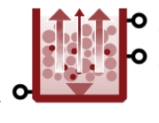
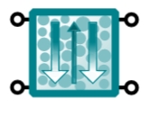
Upflow Biological Aerated Filter using the SumoBioFilm model with fixed film thickness. |
|---|
This bioreactor is an upflow biological filter with two vertical biofilm reactor zones, aerated either in the bottom (resulting in a fully aerated configuration) or at mid height (denitrifying configuration). Aeration is diffused, alpha factor can be predicted or input, identically to the CSTR model.
DO control options:
- Calculated DO (DO is calculated based on input air flow by proper gas transfer description)
- DO controlled in bulk (DO is set and input air flow requirement is calculated based on proper gas transfer description)
Backwash is simulated as a continuous process flow.
For more details, please refer to the Process unit descriptions page.
¶ Digester
|
|
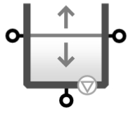
Ideally mixed closed tank with fixed gas volume above the sludge and proper gas transfer calculations. |
|---|
This unaerated bioreactor can be used for modeling anaerobic sludge stabilization or fermentation processes.
¶ MABR
|
|
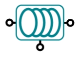
Membrane Aerated Biofilm Reactor using the SumoBioFilm model with fixed film thickness. |
|---|
The membrane aerated biofilm reactor model offers variable oxygen transfer through the membrane.
The biofilm is distributed into layers and diffusion, internal solid transfer, displacement, attachment and detachment is calculated as transport processes between the layers and between the outer layer and the bulk phase.
Diffused aeration is available in the bulk phase, with the following DO control options:
- Calculated DO (DO is calculated based on input air flow by proper gas transfer description)
- DO controlled in bulk (DO is set and input air flow requirement is calculated based on proper gas transfer description)
The alpha factor can be predicted or input, identically to the CSTR model.
¶ Granular SBR
|
|
|
Sequencing batch reactor with ideally mixed bulk phase and granular biofilm extension (fixed film thickness). |
|---|
The fixed volume, sphere like granules are distributed into equal thick layers and diffusion, internal solid transfer, displacement, attachment and detachment is calculated as transport processes between the layers and between the outer layer and the bulk phase.
Two modes of SBR operation are offered:
- Conventional granular SBR (feeding into the mixed tank during reaction phase)
- Aerobic Granular Sludge reactor (feeding to the bottom during decanting phase)
- Flexible granular SBR (cycle setup is flexible)
Diffused aeration is available in the bulk phase, with the following DO control options:
- Calculated DO (DO is calculated based on input air flow by proper gas transfer description)
- DO controlled in bulk (DO is set and input air flow requirement is calculated based on proper gas transfer description)
The alpha factor can be predicted or input, identically to the CSTR model.
¶ UASB
|
|
Upflow Anaerobic Sludge Blanket reactor (built upon the anaerobic digester model). |
|---|
The UASB model in Sumo was developed in two versions with different complexity levels:
- Simple (completely mixed approach)
- Three compartment (for modeling stratification)
For more details, please refer to the Process unit descriptions page.
¶ Trickling filter
|
|
Trickling filter using SumoBioFilm with fixed film thickness and controlled DO transfer. |
|---|
Trickling filter is a complex process unit. The whole volume of the filter is divided into top, middle and bottom sections and using the effluent of the top as influent of the lower units. The media is described with the specific surface and volume fill ratio specified by the type of the media used in the system.
The biofilm is distributed into layers whereas diffusion, internal solid transfer, displacement, attachment and detachment is calculated as transport processes between the layers and between the outer layer and the bulk phase. The bulk phase volume is negligible from the biological activity point of view.
¶ Denite filter
|
|
Tertiary treatment process unit to describe denitrification filter simulation with. |
|---|
Denite filter is a complex unit with simplified process approach in a single reactive compartment setup. It comes with flexible backwash and aeration setup: continuous operation or intermittent depends on dynamic user input. The solids retention is a mass balance based algebraic model offering the following input parameter combinations:
- fixed effluent solids
- fixed solids removal efficiency
¶ MBR
|
|
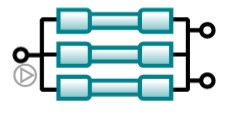
Membrane BioReactor with fixed or variable volume and ideally mixed concentration. |
|---|
The membrane bioreactor model consists of a constant or variable volume aerated reactor (with coarse diffuse aeration system) and an ideal point separator with user-specified effluent solids concentration.
Dissolved oxygen handling:
- input DO (air flow requirement is calculated based on proper gas transfer)
- calculated DO (DO is calculated based on input air flow and proper gas transfer description)
- fixed DO (DO is fixed, without accounting for dynamics, while theoretical required airflow is calculated with the built-in aeration model)
For variable reactor volume, only the calculated DO option is available. The alpha factor can be predicted or input, just like in the CSTR model.
¶ Pond
|
|
|
|
Pond/lagoon with variable volume sludge and water subcompartments. |
|---|
The pond/lagoon model is available in two levels of complexity. The Gen2 model can be aerated mechanically or with a diffuser system and does not consider heat balance or algae growth. The Gen3 model considers the latter two and features mechanical aeration. Detailed description of these models can be found in the Process unit descriptions chapter.
¶ Flow elements
¶ Influent
The influent represents the incoming sewage flow to the plant. In this process unit we define the composition of the incoming wastewater based on COD (preferred method, as mass balance can be performed on this basis) or BOD&TSS. Three types of influent specification are offered by Sumo:
- Concentration based (specify concentrations of a few key components combined with influent fractions)
- Mass flow based (specify mass flows of a few key components combined with influent fractions)
- State variable based (specify the concentration of every state variable)
Most often the concentration based option is used (also being the default choice). For this type of influent, a handy Influent tool is provided as guidance on setting the proper influent fractions, based on available lab data and common values in the US. The mass flow based option might be better suited for specific applications, while the state variable based option comes handy e.g. when simulation results from one modeled plant are to be transferred to another plant model.
If pH is considered for the modeling, the pH specification can be done by following approaches:
- Input pH and alkalinity
- Input cations and CO2
¶ Primary effluent
Similar to the influent process unit, but representing effluent from primary settlers. The specification options are identical to the influent and a dedicated Primary effleunt tool is also available.
¶ Carbon dose
The carbon unit can be used to dose three types of carbon sources:
- Methanol
- Volatile fatty acids (VFA)
- Readily biodegradable substrate (non-VFA)
The dosage type can be concentration or mass flow.
¶ Metal dose
The metal unit can be used to dose the following metal salts:
- AlCl3
- Al2(SO4)3
- FeCl2
- FeCl3
- FeSO4
- Fe2(SO4)3
The metal dose inputs can be provided based on the following options:
- concentration based (flow rate is input, m3/d)
- mass flow based (mass flow is input, kg/d)
For the above options the concentration of the chemical is an input. The following choices are available
- Concentration of dosed element (g element/m3)
- Concentration of salt (g component/m3)
- % by mass of salt and liquid density (% by mass and kg/m3 of solution)
Any combination of the above can be used.
An empirical metal dosage option is available for the ASM2D Museum model.
¶ Chemicals
The chemicals unit can be used to dose the following chemicals:
- Caustic
- Ammonium bicarbonate
- Calcium chloride
- Calcium hydroxide
- Magnesium chloride
- Magnesium hydroxide
- Nitric acid
- Phosphoric acid
- Potassium nitrate
- Potassium nitrite
- Sodium bicarbonate
- Sodium carbonate
- Sulfuric acid
The chemical dose inputs can be provided based on the following options:
- concentration based (flow rate is input, m3/d)
- mass flow based (mass flow is input, kg/d)
For the above options the concentration of the chemical is an input. The following choices are available
- Concentration of dosed element (g element/m3)
- Concentration of salt (g component/m3)
- % by mass of salt and liquid density (% by mass and kg/m3 of solution)
Any combination of the above can be used.
¶ Water
Specific process unit to represent clean washwater inputs on the drawing board. State variables are set to non-detect values, while the alpha factor is set to 1. Component concentrations can be customized, nevertheless.
¶ Effluent
Specific process unit to represent effluent flow leaving the plant. There are no specifications for this unit as it is used solely for reporting results.
¶ Sludge
Specific process unit to represent sludge flow leaving the plant. Four types of sludges can be specified, the choice will only have effect on the operational cost estimations (via disposal fees):
- Screening
- Grit
- Grease
- Sludge
¶ Product
Specific process unit to represent marketable product flow (i.e. from P recovery) leaving the plant. There are no specifications for this unit as it is used solely for reporting results.
¶ Sludge feed
Specific process unit to represent sludge input flows when only the sludge treatment is the aim of the modeling. Four types of sludge can be specified:
- Thickened primary
- Thickened waste activated sludge
- Food waste
- Thickened primary and waste activated sludge
In the case of food waste, five additional types can be specified:
- Organic fraction of municipal
- Meat-rich
- Dairy-rich
- Fruit and sugar rich
- Vegetable rich
Typical concentrations and influent fractions are preconfigured according to the choices made.
¶ Dividers
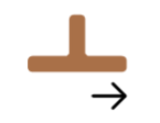
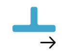
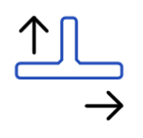
In most cases, the plant layout employs flow dividers. Sumo offers two geometric variants for these, with the same underlying model:
- Side flow divider
- T flow divider
The flow split between the two outgoing pipes can be specified as:
- pumped: a fixed pumped flow is routed to one pipe (denoted by pump sign), while the remaining (if any) is routed to the other pipe (denoted by grey arrow)
- proportional: a fixed fraction of the incoming flow is routed to one pipe (denoted by pump sign and red arrow), while the remaining is routed to the other pipe (denoted by grey arrow)
The operation of the dividers can be specified as:
- continuous (pump cycling Off)
- cyclic (pump cycling On)
¶ Combiners
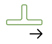
In most cases, the plant layout employs flow combiners. Sumo offers three geometric variants for these, with the same underlying model:
- Side flow combiner (adjoining two incoming flows arriving from prependicular pipes)
- T flow combiner (adjoining two incoming flows arriving from two pipes facing each other)
- Multi flow combiner (adjoining three incoming flows)
¶ Equalization basin
|
|
Variable volume tank with ideally mixed concentration, featuring pumped output and overflow for flow balancing. |
|---|
This process unit can be set up to be reactive or non-reactive (note that the latter is the default setting). In most aspects it behaves - and can be configured - just like a CSTR, apart from the DO handling (which is always calculated) and the flow dynamics (the EQ tank has a fixed pumped output flow and overflows if the predefined volume is exceeded).
¶ Separators
¶ Screen
|
|
Mass balance based volumeless point separator model with specified percent solids removal and underflow solids concentration. |
|---|
¶ Grit chamber
|
|
Mass balance based volumeless point separator model (vortex grit chamber) with specified input VSS increment or removed grit mass. |
|---|
¶ Grease trap
|
|
Mass balance based volumeless point separator model with specified percent FOG (fat, oil and grease) removal and removed FOG flow fraction. |
|---|
¶ Primary
 |
High-efficiency primary settler model with options for three levels of complexity (volumeless point separator, three-compartment model and 1D layered flux model). |
|---|---|
|
|
Conventional primary settler model with options for three levels of complexity (volumeless point separator, three-compartment model and 1D layered flux model). |
Primary separation efficiency type can be switched between conventional and high efficiency in the ‘Efficiency type’ attribute. Polymer addition is considered by default for high-efficiency primary settlers , and the dosage is an input parameter.
Volumeless model:
Conventional unit employs mass balance based algebraic models with various input parameter combinations:
- fixed sludge flow and effluent solids concentration
- fixed sludge flow with percent solids and colloidal removal
- fixed sludge flow with specified solids percent removal and VSS/TSS ratio increase in effluent
- fixed sludge solids concentration with specified solids percent removal and VSS/TSS ratio increase in effluent
High-efficiency unit employs mass balance based algebraic models with fixed sludge flow with specified solids/colloidal percent removal. The entire unit is non-reactive by default, and polymer dosage is for cost calculation purpose only.
Three-compartment model:
Both conventional and high-efficiency units consist of a feed well, a clear water compartment and a sludge blanket (offering reactive volumes for each), interconnected with volumeless point separator models (more details on this can be found in the Process unit specific models chapter). In the feed well, polymer can be added. An elutriation flow allows natural or forced circulation of flow from sludge blanket to clear liquid to account for the diffusion of soluble components. Sumo offers three-compartment primary models with the following input parameter combinations:
- fixed sludge solids concentration with solids percent removal and VSS/TSS ratio increase in effluent
- fixed sludge flow with specified solids percent removal and VSS/TSS ratio increase in effluent
1D layered model:
Conventional 1D layered unit employs a triple exponential settling velocity model that handles the solid flux exchanges among the various layers of the settler volume (the number of layers is customizable) and predict effluent solids concentration (more details on this can be found in the Process unit specific models chapter). The volume is reactive by default but can be set to non-reactive as well. The positioning (depth) of the feed and the sludge flow are to be specified by the user. Settling parameters can be derived from zone settling lab tests (for this purpose a Vesilind settling parameters tool is provided).
High-efficiency 1D layered unit employs a triple exponential settling velocity model that handles the solid flux exchanges among the various layers of the settler volume (the number of layers is customizable) and predicts effluent solids concentration (more details on this can be found in the Process unit specific models chapter). The volume is reactive by default. An increasing factor is employed to calculate the project surface area (enhanced by lamella structure), positioning (depth) of the feed and the sludge flow are to be specified by the user. Settling parameters can be derived from zone settling lab tests (for this purpose a Vesilind settling parameters tool is provided).
¶ Clarifier
 |
High-efficiency clarifier model with options for three levels of complexity (volumeless point separator, three-compartment model and 1D layered flux model). |
|---|---|
|
|
Conventional clarifier model with options for three levels of complexity (volumeless point separator, three-compartment model and 1D layered flux model). |
Clarifier separation efficiency type can be switched between conventional and high efficiency in the ‘Efficiency type’ attribute. Polymer addition is considered by default for high-efficiency clarifiers, and the dosage is an input parameter.
Volumeless model:
Conventional unit employs mass balance based algebraic models with various input parameter combinations:
- fixed sludge flow with specified effluent solids
- fixed effluent solids with specified sludge concentration
- fixed sludge flow with specified solids percent removal efficiency
High-efficiency unit employs mass balance based algebraic models with fixed sludge flow with specified solids/colloidal/soluble material percent. The volume is non-reactive by default, and the polymer dosage is only for cost calculation purpose.
Three-compartment model:
Both conventional and high-efficiency units consist of a feed well, a clear water compartment and a sludge blanket (offering reactive volumes for each, except for the clear phase of the conventional clarifiers), connected with volumeless point separators (more details on this can be found in the Process unit specific models chapter). In the feed well, polymer can be added. Sumo offers three-compartment models for final-stage and A-stage clarifiers with the following input parameter combinations:
- A-stage with specified sludge concentration and fixed solids removal efficiency
- A-stage with specified sludge flow and fixed solids removal efficiency
- Final-stage with fixed effluent solids and specified sludge flow
- Final-stage with fixed effluent solids and fixed sludge concentration
- Final-stage with fixed solids removal efficiency and specified sludge flow
In the A-stage clarifiers, an elutriation flow allows natural or forced circulation of flow from sludge blanket to clear liquid to account for the diffusion of soluble components.
1D layered model:
Conventional unit employs a triple exponential settling velocity model that handles the solid flux exchanges among the various layers of the settler volume (the number of layers is customizable) and predict effluent solids concentration (more details on this can be found in the Process unit specific models chapter). The volume is non-reactive by default but can be set to reactive as well. The positioning (depth) of the feed and the sludge flow are to be specified by the user. Settling parameters can be estimated from SVI(and vice versa) or derived from zone settling lab tests (for this purpose a Vesilind settling parameters tool is provided).
High-efficiency unit employs a triple exponential settling velocity model that handles the solid flux exchanges among the various layers of the settler volume (the number of layers is customizable) and predict effluent solids concentration (more details on this can be found in the Process unit specific models chapter). The volume is reactive by default. An increasing factor is employed to calculate the project surface area (enhanced by lamella structure), positioning (depth) of the feed and the sludge flow are to be specified by the user. Settling parameters can be estimated from SVI (and vice versa) or derived from zone settling lab tests (for this purpose a Vesilind settling parameters tool is provided).
¶ DAF
|
|
Mass balance based volumeless model of Dissolved Air Flotation for simultaneous solids and FOG (fat, oil and grease) removal. |
|---|
The mass balance based algebraic DAF models offer the following input parameter combinations:
- fixed effluent solids concentration and sludge flow with specified FOG removal efficiency
- fixed solids removal efficiency and sludge flow with specified FOG removal efficiency
- fixed solids removal efficiency and sludge concentration with specified FOG removal efficiency
¶ Thickener
|
|
Thickener model with options for three levels of complexity (volumeless point separator, three-compartment model and 1D layered flux model). |
|---|
Volumeless units employ mass balance based algebraic models with various input parameter combinations:
- fixed effluent solids with specified thickened sludge flow
- fixed solids percent removal efficiency with specified thickened sludge concentration
- fixed solids percent removal efficiency with specified thickened sludge flow
Three-compartment units consist of a feed well, a clear water compartment and a sludge blanket (offering reactive volumes for each, except for the clear phase), interconnected with volumeless point separators (more details on this can be found in the Process unit specific models chapter). In the feed well, polymer can be added. An elutriation flow allows natural or forced circulation of flow from sludge blanket to clear liquid to account for the diffusion of soluble components. Sumo offers three-compartment thickener models with the following input parameter combinations:
- fixed solids percent removal efficiency with specified thickened sludge concentration
- fixed solids percent removal efficiency with specified thickened sludge flow
The 1D layered model employs a triple exponential settling velocity model that handles the solid flux exchanges among the various layers of the settler volume (the number of layers is customizable) and predict effluent solids concentration (more details on this can be found in the Process unit specific models chapter). The volume is non-reactive by default but can be set to reactive as well. The positioning (depth) of the feed and the sludge flow are to be specified by the user. Settling parameters can be derived from zone settling lab tests (for this purpose a Vesilind settling parameters tool is provided).
¶ Dewatering
|
|
General and predictive volumeless models for describing sludge dewatering processes. |
|---|
The two general volumeless units employ mass balance based algebraic models with the following input parameter combinations:
- fixed solids percent removal efficiency with specified dewatered cake solids concentration
- fixed solids percent removal efficiency with specified sludge flow
The two advanced volumeless units employ a mechanistic modelling approach to simulate and predict sludge bound water content and dewaterability for various types of dewatering units:
- Centrifuge
- Beltfilter press
- Screw press
- Crown press
¶ Sand filter
|
|
Mass balance based volumeless point separator model with backwash flow. |
|---|
The mass balance based algebraic model considers the net result of filter operation (no intermittent stages), offering the following input parameter combinations:
- fixed effluent solids concentration and colloids removal efficiency
- fixed solids and colloids removal efficiency
¶ Disc filter
|
|
Mass balance based volumeless point separator model with internal backwash flow. |
|---|
The mass balance based algebraic model considers the net result of filter operation (no intermittent stages), offering the following input parameter combinations:
- fixed effluent solids and backwash flow
- fixed solids removal efficiency and backwash flow
¶ Cyclone
|
|
Mass balance based volumeless point separator model with specified underflow fraction and state variable separation. |
|---|
This mass balance based algebraic model offers two options:
- general state variable separator (specify fixed removal efficiency for any SV as input)
- anammox cyclone (with specified inorganic solids and annamox removal efficiency as inputs)
¶ RO - available on demand for Sumo22 users
|
|
Simplified volumeless membrane separator model without surface area, designed for modelling RO mass balance and scaling risk. |
|---|
Sumo offers a simple mass balance based RO model with the internal structure and specification options outlined below. The model can deal with multiple parallel trains of RO regarding pumps.
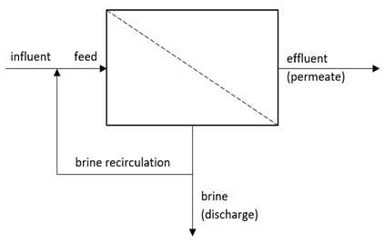
| Recovery options | Brine recirculation options |
|---|---|
|
|
¶ Point separator
|
|
Ideal, mass balance based volumeless solids separator unit with various specification options available, as listed out below. |
|---|
- perfect separator with specified recycle flow
- fixed effluent solids
- fixed effluent solids and proportional underflow
- fixed solids removal efficiency
- fixed solids removal efficiency and proportional underflow
¶ Special units
¶ AS design
|
|
Activated sludge design example to demonstrate the algebraic model capabilities of Sumo. Simple AS design to calculate reactor volume and sludge production from design load, SRT and MLSS. |
|---|
¶ AOP
|
|
Advanced oxidation process to convert soluble unbiodegradable organic material into biodegradable fractions. |
|---|
¶ Deflocculator
|
|
Deflocculator is a process unit to mimic the impact of pumping on sludge: it break the structure of flocs and increases the colloidal fraction in the wastewater, developed for Sumo2C model. |
|---|
¶ P recovery
|
|
|
Dedicated process unit for phosphorus recovery technology producing struvite of calcium phosphate. |
|---|
Two phosphorus recovery units have been developed to be able to simulate several commercialized processes:
- the first process unit uses magnesium dosage (magnesium chloride and magnesium hydroxide),
- the second one uses calcium dosage (Calcium chloride and calcium hydroxide).
In both, aeration to strip bicarbonate for pH increase and a caustic dosage are available.
The following dosage options are available:
- With Mg(OH)2 and MgCl2
- With Ca(OH)2 and CaCl2
The chemical dose inputs can be provided based on the following options:
- concentration based (flow rate is input, m3/d)
- mass flow based (mass flow is input, kg/d)
For the above options the concentration of the chemical is an input. The following choices are available
- Concentration of cation (Mg or Ca as element)
- Concentration of salt (Mg(OH)2, MgCl2, Ca(OH)2 and CaCl2)
- % by mass of salt and liquid density
Any combination of the above can be used.
¶ Temperature adjustment
|
|
The temperature adjustment unit is prepared to calculate the energy demand of increasing the temperature of a liquid stream. |
|---|
¶ THP
|
|
The THP, alias thermal hydrolysis unit describes the physical processing of sludge. An algebraic calculation is used to model impact on particulate material solubilization under technology specific thermal and pressure conditions. The particulate matter is converted into soluble components. |
|---|
¶ Catchments and rivers
The catchments and rivers extension in Sumo enables the user to handle sewers, plant and river within the same configuration. This feature employs two simplified process models (one for urban sewer system and another for river system) integrated into the process units, which can be connected to the standard full-plant Sumo models using model connectors.
¶ Urban catchment
|
|
Simple urban catchment with empirical infiltration model and dry weather flow plus runoff generation involving depression storage, evaporation and catchment hydrology (represented by runoff tank). Collection system is represented as on-line volume. |
|---|
¶ River catchment
|
|
Simple river catchment (natural watershed) with empirical infiltration and base flow model plus runoff generation involving depression storage, evaporation and catchment hydrology (represented by runoff tank). |
|---|
¶ Circular pipe
|
|
Circular pipe with overflow and backwater effect for urban sewer system with solids sedimentation and mixing. |
|---|
¶ Pipe tank
|
|
Rectangular pipe with overflow and backwater effect for urban sewer system with solids sedimentation and mixing. |
|---|
¶ Off-line tank
|
|
Variable volume off-line tank model with overflow and simple screen for urban sewer system. |
|---|
¶ Influent sewer
|
|
State variable based simple influent process unit customized for urban sewer system. |
|---|
¶ River stretch
|
|
River stretch with simple biokinetics (nitrification and BOD reactions, reaeration, photosynthesis/respiration), BOD sedimentation and hydraulics modeled as channel flow, featuring a dedicated port for sewage/WRRF effluent input (discharge). |
|---|
¶ Sewer combiner
|
|
Simple flow combiner process unit to be used with urban sewer system elements. |
|---|
¶ River combiner
|
|
Simple flow combiner process unit to be used with river system elements. |
|---|
¶ Sewer_WRRF connector
|
|
Connector process unit for interfacing between urban sewer system and Sumo models (handling state variable conversions). |
|---|
¶ Sewer_River connector
|
|
Connector process unit for interfacing between urban sewer system and river models (handling state variable conversions). |
|---|
¶ WRRF_River connector
|
|
Connector process unit for interfacing between Sumo and river models (handling state variable conversions). |
|---|
¶ Influent generator dynamic
|
|
Intrinsic model for synthetising dynamic flow and pollutant mass flows from daily averages using dilution, replenishment and resuspension caused by large, medium and small events. |
|---|
¶ Meteo box
|
|
Special unit for meteorological parameters that can be used for collective weather parameter mapping. |
|---|
¶ Energy units
¶ Aeration units
¶ Blower energy calculator
|
|
|
|
Blower energy calculator unit to calculate the power demand of the process required airflow. |
|---|
The unit is called Blower energy calculator as it is using the process model calculated input air flow and defines the blower operation point to calculate the power demand and energy consumption. Undersized blower will not impact the performance of the process model but will indicate the fact of undersized blower.
Three type of energy calculation option is available based on:
- empirical model (considering input efficiency model for pneumatic power demand)
- positive displacement blower (detailed blower curves to calculate blower efficiency and power demand)
- turbo blower (detailed blower curves to calculate blower efficiency and power demand)
¶ Production units
¶ CHP
|
|
Combined heat and power generation unit using input efficiency or calculated efficiency model to estimate the electric power and heat generation capability of the facility. |
|---|
The generated power and heat is calculated based on methane mass flow from the process model. The efficiency is defined as input parameter or can be calculated based on performance curve of the CHP unit.
Efficiency calculation options:
- Input efficiency
- Calculated efficiency
¶ Gastank
|
|
Biogastank with integrated gas composition model using input gas flow parameter and allowing overflow biogas to flare. |
|---|
¶ Flare
|
|
Simple flare unit to indicate if any gas is burned outside the CHP unit. Uses input methane gas mass flow and participates in greenhouse gas emission calculation. |
|---|
¶ Connectors
¶ Air connector
|
|
Airflow connector to allow to supply multiple aerated tanks from a single blower group. |
|---|
¶ Biogas flow combiner
|
|
Biogas flow combiner to allow the connection of multiple digesters or UASB units to a single biogas tank or CHP unit. |
|---|
¶ Biogas flow divider
|
|
Biogas flow divider to allow the supply of different biogas tanks or CHP units from a single digester/UASB unit. |
|---|
Flow split options are:
- Flow based ("pumped" biogas flow is the input parameter)
- Proportional (fraction of input flow is the input parameter)
¶ Plantwide units
The goal of plantwide units is to allow the user to set up calculation between different units in the same project. Typical usecases are controllers where the control variable may be at different location as the manipulated variable.
¶ Controllers
¶ Continuous P controller
|
|
The continuous P controller is using the proportional part of the discrete PID controller. It is continuous as the manipulated variable is handled as state variables: it is recalculated every integration step. |
|---|
¶ Deadband controller
|
|
Deadband controller can be configured to switch the manipulated variable between a lower and higher value based on the value of the control variable compared to a control range. |
|---|
¶ PID controller
|
|
Discrete PID controller, velocity form. The manipulated variable is recalculated at every predefined time step. Proportional, integral and derivative gains are input parameters. |
|---|
¶ Ratio controller
|
|
Ratio controller is a continuous controller where the manipulated variable value and the control variable ratio is fixed through a user defined parameter value. |
|---|
¶ Switch controller
|
|
Switch controller continuously changes the manipulated variable between two values depending on the control variable value compared to a threshold. |
|---|
¶ Time based on-off controller
|
|
Time based on/off controller changes the manipulated variable between two values based on user defined cycles. |
|---|
¶ Statistics
Statistical units are helpful tools to generate results from the simulation in the form they are needed for comparison with measurements.
¶ Cycle based totalizer
|
|
Cycle based totalizer integrates a variable for the cycle time set up by the user. It can provide the total daily flow from an hourly based dynamic input table of influent flow. |
|---|
¶ Min/Max
|
|
Min/Max unit is a continuous value sampling unit which every step stores the minimum and maximum variable value of the simulation period and provides it as output for the user. |
|---|
¶ Moving average
|
|
Moving average unit is a discrete value sampling unit which every given timestep stores the variable value and provides the average for the user defined average time period. |
|---|
¶ Noise
|
|
Noise unit places measurement noise upon a variable. The noise can be white or Gaussian. |
|---|
¶ Response time
|
|
The response time unit applies a zero order delay function on the measured variable to mimic the impact of sensor response time. |
|---|
¶ Totalizer
|
|
Totalizer unit integrates a selected variable for the simulation time. |
|---|
